Firmware &
Software
Page 2
touch
Touchscreen capability was specifically chosen for the Embedded Resume Device to provide a more enriching user experience.
Reading Touch Attributes
Although a fancy capacitive-touch model would have been nice, I had to settle on a resistive version that met my price point. This type of device has two films stacked on top of each other. Each layer has a pair of pins (X+/- and Y+/-) which form a voltage divider on their individual sheet. When the user touches the screen, the two films meet at a common point and both sets of voltage dividers connect at a central node. Take a look at the diagram below.
Depending on how we configure the pins, we can observe different attributes of the user’s touch. In order to read the X position, we simply tie X+ to 3.3v and X- to GND. This forms a voltage divider on the X sheet. As the user presses the screen, the two sheets touch, and we are able to use an analog input pin (Y+ here) to measure its voltage.
/*!
* @brief Sample Y_PLUS and return the corresponding x position
* @param[in] NONE
* @return  NONE
*/
uint16_t
touch_read_x_position(void)
{
   //Disable ADC to change settings
   adc_disable();

   //Sample a single channel Y+
   ADC1->SQR1 &= ~(0xFF << 20);

   //Set scan order to scan PA2 (Y+)
   ADC1->SQR3 &= ~0x1F; //Clear register
   ADC1->SQR3 |= (ADC_SQR3_SQ1_CHANNEL2);

   //set gpios to read x position
   gpio_func_init(TOUCH_Y_PLUS, GPIO_MODER_ANALOG);//Set pins to analog mode
   gpio_pupd_init(TOUCH_Y_PLUS,GPIO_PUPDR_NONE);//No pull up/pull down
   gpio_speed_init(TOUCH_Y_PLUS,GPIO_OSPEEDR_LOW);//Low speed

   gpio_gen_output_init(TOUCH_X_PLUS);
   gpio_gen_output_init(TOUCH_X_MINUS);
   gpio_gen_input_init(TOUCH_Y_MINUS); //high z
   gpio_set(TOUCH_X_PLUS); //X+ = 3.3v
   gpio_clear(TOUCH_X_MINUS); //X- = 0v

   //Enable ADC after settings change
   adc_enable();

   //Start conversion
   ADC1->CR2 |= ADC_CR2_SWSTART;

   //Poll for end of conversion
   while(!((ADC1->SR & ADC_SR_EOC) >> ADC_SR_EOC_Pos));

   //Get data for channel 0
   volatile uint16_t tmp_sample_value = 0;
   tmp_sample_value = ADC1->DR;

   //Clear status flags
   ADC1->SR = 0;

   //Disable ADC to change settings
   adc_disable();

   return(tmp_sample_value);
}
This function does exactly that. It starts by configuring the GPIOs as described and then uses the STM32’s ADC to get a voltage reading. The Y position is found using a nearly identical method.
/*!
* @brief Puts the LCD in idle state, which waits for a user to touch the screen and trigger an interrupt
* @param[in] NONE
* @return  NONE
*/
void
touch_idle_state(void)
{
   //Initialize gpios
   gpio_gen_input_init(TOUCH_X_PLUS); //Interrupt pin
   gpio_gen_output_init(TOUCH_Y_MINUS); //0v
   gpio_gen_input_init(TOUCH_Y_PLUS); //high z

   gpio_gen_output_init(TOUCH_X_MINUS); //3.3v pull up
   gpio_type_init(TOUCH_X_MINUS, GPIO_OTYPER_OPEN_DRAIN); //To work correctly with pullup
   gpio_pupd_init(TOUCH_X_MINUS, GPIO_PUPDR_PULL_UP);

   //Set X_PLUS as an interrupt
	EXTI -> IMR |= EXTI_IMR_IM1; //Unmask interrupt pin 1

   //Set pins to logic state
   gpio_clear(TOUCH_Y_MINUS);
   gpio_set(TOUCH_X_MINUS);
}
We have one more trick up our sleeves. The code above puts the touchscreen module in an idle state, meaning that it is not in use. If we look back at the configuration diagram, we see that X+ is now open drain with a pull-up resistor and X- is actually tied to an interrupt pin. Equally as important, Y- is now sitting at GND. What does this odd configuration do?
When the screen is sitting unused in this setup, the pullup resistor keeps X- logic high (3.3v). If the user touches the screen, a path to GND will be formed from X+ through Y-. Since the pull-up resistor is a large value (in the 10s of kΩ) compared to the touchscreen (< 1kΩ), it will drop almost the entire 3.3v, meaning the center node (and therefore X-) will drop to nearly 0v. This change is used to trigger an interrupt in the MCU. We’re going to use this interrupt to tell if the user has touched the screen to avoid wasting processor cycles constantly reading the ADC to see if anything changed.
/*!
* @brief Get both x and y position from the LCD
* @param[in] NONE
* @return NONE
* NOTE: This is meant to be used in a multi-threaded system, meaning that it should be
*       called (serviced) every iteration of the containing for{} loop. The position will
*       only update if a touch occurs, triggering the ISR and setting the touch_detection
*       flag. If no touch has occurred, position (0,0) will be returned.
*/
void
touch_update_position(void)
{

   if(touch_detection == 1)
   {
      EXTI -> IMR &= ~EXTI_IMR_IM1; //Mask interrupts from touch_detection pin

      //Take samples
      uint16_t adc_y_sample = touch_read_y_position();
      uint16_t adc_x_sample = touch_read_x_position();

      /*Calculate corresponding position (x,y) from the raw ADC values
       * adc_y_sample are in the range 360-3720. This remaps them to 0 - 480
       * adc_x_sample are in the range 450-3650. This remaps them to 0 - 320 */
      touch_position[0] = (adc_x_sample - 450) / 10;
      touch_position[1] = (480 - ((adc_y_sample - 360) / 7));

      //Reset ISR flag
      touch_detection = 0;

      //Return to idle state and wait for the next touch-sense interrupt
      touch_idle_state();
    }

   else
   {
      //If no touch has occurred, reset the position to (0,0)
      touch_position[0] = 0;
      touch_position[1] = 0;
   }

   //Bounds check, the screen is 320 x 480
   if((321 < touch_position[0]) || (480 < touch_position[1]))
   {
      touch_position[0] = 0;
      touch_position[1] = 0;
   }
}
This function is serviced every iteration of the main loop and is a culmination of all the methods mentioned above. Whenever the user touches the screen and triggers an interrupt, the touch_detection flag is set to “1”. The function then reads the current Y position, reconfigures the touch pins’ GPIO, and reads the X position. All of this happens so fast (for humans) that it appears as if the two readings are happening simultaneously.
It then takes the raw ADC voltages (2.3v for example) and remaps them to a useable pixel position on the screen (something like [280, 105]). Finally, it puts the system back into idle state and waits for another screen touch. Using this method, the MCU can keep track of all user screen touches.
Micro SD CArd
The SPI has been physically connected to our Micro SD Card and we’ve already written a driver for it, but we still need to create a module for actually communicating with the card itself.
Startup Routine
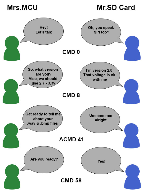
SD Cards are a bit picky when it comes to booting them up. You should take a look at the SD Specifications for the exact details, but to summarize, we have to do an initial handshake with the card by sending a series of commands over SPI. These establish common settings, so the MCU and SD Card are on the same page when transferring data.
I will point you to one of the best articles that I have seen on initializing an SD Card, as opposed to less eloquently recreating it here. I also made an amusing cartoon that summarizes the basic idea below.
/*!
* @brief Initializes the MCU's gpio, defines transfer settings and does the initial handshake with the SD card
* @param[in] NONE
* @return  init_success if successful this will be 1, otherwise 0;
*
* NOTE: SPI2_CS is not hardware controlled and must be managed in software
*
*/
uint8_t
microsd_init(void)
{

   //Make it easy to identify the start of init on the PC serial terminal
   uart1_printf(" \n\r-----------------SD CARD INITIALIZATION----------------- \n\r" );
   uart1_printf(" -------------------------------------------------------- \n\r" );
   uart1_printf(" -------------------------------------------------------- \n\r" );

   uint8_t init_success = 1;

   //Start contact with SD card and put it in idle state
   init_success = sd_idle_sequence();

   //Verify SD version greater than 2.0 and confirm voltage of 3.3v is acceptable
   init_success = sd_interface_condition_sequence();

   //Read OCR for power status and acceptable voltage
   sd_read_ocr();

   uint16_t timeout_count = 0;

   //Send command to begin SD card initialization
   //Repeat ACMD41 until card is out of idle or timeout is reached
   while(!(sd_send_operating_condition()))
   {
      timeout_count++;

      if(200 < timeout_count)
      {
         break;
      }
   }

   //Check OCR to see if card is high capacity
   init_success = sd_read_ocr();

   //Read the file address lookup table and send them to their corresponding structures
   sd_import_file_addresses();

   //If there were no errors, this should still be 1
   return(init_success);
}
Reading & Writing Data
Now that everything is initialized, how do we actually go about transferring data? Well first, let’s take a look at the layout of memory inside an SDHC Card.
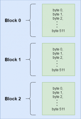
Data is arranged in something called blocks, which is a fancy way of saying groups of 512 bytes (for SDHC). Looking at the diagram to the right, we see that the blocks are arranged one after the other and each contains a memory address. This is important because we need to know the exact address of the file that we want to read/write.
The address itself is a 32-bit number and it references the block, not the actual bytes. For example, if I wanted to access the fifth byte of block 27, I would send address 27. This brings up another important point; only an entire memory block can be written at any one time. If we want to change any of the bytes inside a block, we must read the entire block to the MCU’s RAM, change the byte(s) we want, then write it back to the same address.
/*!
* @brief Write a single block (512bytes for SDHC) to the SD card
* @param[in] tmp_write_buffer Data that will be written to the sd card
* @param[in] block_address Address of desired block.
* @return  NONE
*/
void
sd_write_block(uint8_t *tmp_write_buffer, uint32_t block_address)
{

   //Wrap CS transition in dummy bytes to make sure SD card acknowledges it
   spi_send_byte(0xFF);
   gpio_clear(SPI2_CS);
   spi_send_byte(0xFF);

   //Send CMD24, aka WRITE_SINGLE_BLOCK
   sd_send_command(24,block_address);
   spi_send_byte(SD_DUMMY_CRC);

   //Receive R1 response
   spi_receive_byte(0xFF); //dummy byte. SD card responds only after 8 clocks
   sd_receive_r1_response();
   sd_receive_r1_response();

   //Send start block token
   spi_send_byte(SD_CMD17_TOKEN); //CMD17 token is the same as CMD24 token

   //Send all 512 bytes
   for(uint16_t current_byte = 0; current_byte < 512; current_byte++)
   {
      spi_send_byte(tmp_write_buffer[current_byte]);
   }

   sd_cmd24_termination_sequence();

   //Wrap CS transition in dummy bytes to make sure SD card acknowledges it
   spi_send_byte(0xFF);
   gpio_set(SPI2_CS);
   spi_send_byte(0xFF);
}
The code above does just this. It gives the SD Card the WRITE_SINGLE_BLOCK command and waits for an acknowledge response. This tells the card that we are going to send it 512 bytes and that it should place these in the address we specified. Finally, we send a start token (to announce that we are beginning the transfer) and push our buffer over SPI.
/*!
* @brief Tell the SD card to continue sending data until told to stop
* @param[in] start_address
* @return  NONE
*
* WARNING: start_address is the address of the entire 512-byte block, not each individual byte address
*          For example, to read byte 520, you would set block_address = 1 (address starts at 0)
*
*/
void
sd_read_multiple_block(uint16_t start_address)
{
   uint16_t response_timeout = 0;

   //Wrap CS transition in dummy bytes to make sure SD card acknowledges it
   spi_send_byte(0xFF);
   gpio_clear(SPI2_CS);
   spi_send_byte(0xFF);

   //Send CMD18, aka READ_MULTIPLE_BLOCK
   sd_send_command(18, start_address);
   spi_send_byte(SD_DUMMY_CRC);

   //Receive R1 response
   spi_receive_byte(0xFF); //dummy byte. SD card responds only after 8 clocks
   sd_receive_r1_response();
   sd_receive_r1_response();

   //Wait for the correct token 0xFE
   while((spi_receive_byte(0xFF) != SD_CMD17_TOKEN)) //CMD17 token is the same for CMD18
   {
      response_timeout++;

      if(response_timeout > 6000)
      {
         break;
      }
   }
}
Using roughly the same method, we can read from the SD Card. Although 512 bytes may seem like a lot, that’s only enough to hold 0.001% of an image for the Embedded Resume Device, which often takes up thousands of blocks. Sure, we could read each block one by one, but that would be terribly slow, and our user would get frustrated with lagging menus.
For this reason, we’re going to use the MULTIPLE_BLOCK_READ command. Take a look at the function above. The main difference here is that by giving this command, we tell the card, “continuously send me data starting at this block address and don’t stop until I tell you.” This way we don’t have to waste time constantly feeding the card incrementing addresses.
Making our own File System
(Do not do this…ever)
Modern SD Cards come preformatted with some flavor of the FAT file system, which is extensively popular across the industry. It is one of the best ways to provide a simple, no frills way of allowing your embedded system to keep track of pictures, music, text docs and more.
So now that I’ve told you how great it is, let’s go ahead and forget all about it. We’re going to make our own file system. If you’re an embedded software engineer, you just threw your keyboard at the wall and flashed back to 1990 when every company had their own (terrible) internal OS. I flirted with the idea of using a simple middleware library like the Petit FAT File System Module but didn’t want to waste a couple weeks getting my drivers to play nice with it.
I cannot emphasize how horrible of an idea this is, and if it were a commercial product, I would never be able to do this. In fact, the only reason I’m able to get away with this here is because (a) I’m only making 10 devices, (b) I have strict control over all of the files and direct access to the MCU, and (c) after initial flashing, no files are ever created, deleted, moved, renamed or altered in any way; they are only read.
typedef struct t_sd_file
{
   const e_sd_file_type type;
   const uint8_t identifier[5];
   uint32_t address;
   uint32_t size;

} t_sd_file;
//List of all files on the SD card
//WARNING: The file order must match with the list in enum_sd_file_list.h
static t_sd_file file_list[max_total_addresses] =
{
      {.type = bmp_file, .identifier = {0xDA, 0x52, 0x55, 0x96, 0xD0}, .address = 0}, // skills_arm
      {.type = bmp_file, .identifier = {0x65, 0x20, 0x02, 0x02, 0x98}, .address = 0}, // skills_circuit
      {.type = bmp_file, .identifier = {0x16, 0x00, 0xAF, 0x78, 0x89}, .address = 0}, // skills_github 16

      //All other files were removed for this website example
};
The first question of our file system is how we want to define the files themselves. Since nothing will change after the production flashing, we can declare each one as a simple structure and create a master list in the MCU of all files on the SD Card. The structure has members file type, identifier, address, and size.
We’re not going to overwrite the FAT file system already present on the card because we still want to be able to plug it into our PC and load/edit files. Instead, we’re simply going to snoop around.
/*!
* @brief This does a brute force procedural search of the SD card looking for file identifiers.
*        It then copies the start addresses of each file to a lookup table in the SD card itself
*        at a memory block very far outside of the scope that the FAT32 file system should ever
*        manipulate for this system.
* @param[in] NONE
* @return  NONE
* NOTE: This is very slow yet more maintainable. The function only ever runs once before flashing the main
*       binary just to put the addresses in the sd card. It doesn't even get included in the main binary,
*       so speed is not a great concern.
*
*/
void
sd_search_file_addresses(void)
{
   uint16_t total_files = max_total_addresses;

   lcd_draw_rectangle(0x00, 0, 0, 320, 480);

   //Do a brute force search to find each file starting address
   for(uint8_t current_file = 0; current_file < total_files; current_file++)
   {
      char tmp_string[10] = {0};

      //Send file information to PC console
      pft_uint32_to_string(current_file, tmp_string);
      uart1_printf("Current file number:  ");
      uart1_printf(tmp_string);
      uart1_printf(" \n \r");

      //Display file information on LCD
      lcd_print_string("Current file number: ", 50, 100, 0x03E0, 0x0000);
      lcd_print_string(tmp_string, 50, 120, 0x03E0, 0x0000);

      //Search for current file address
      file_list[current_file].address = sd_find_file_address(file_list[current_file].identifier);

   }

   uint8_t address_buffer[512] = {0}; //Buffer to be written to the SD card file address cheat sheet block

   total_files = (max_total_addresses)*4; // Four bytes per uint32

   //Split each uint32 address into four bytes and store them in the array
   for(uint8_t current_file = 0; current_file < max_total_addresses; current_file ++)
   {
      address_buffer[(current_file*4) + SD_ADDRESS_LIST_OFFSET] = (file_list[current_file].address >> 24);
      address_buffer[(current_file*4) + SD_ADDRESS_LIST_OFFSET + 1] = (file_list[current_file].address >> 16);
      address_buffer[(current_file*4) + SD_ADDRESS_LIST_OFFSET + 2] = (file_list[current_file].address >> 8);
      address_buffer[(current_file*4) + SD_ADDRESS_LIST_OFFSET + 3] = (file_list[current_file].address & 0xFF);
   }

   //Transfer the file addresses to the cheat sheet inside the SD Card
   sd_write_block(address_buffer, SD_ADDRESS_CHEAT_SHEET);
   uart1_printf("\n\r File search complete \n \r");
   lcd_print_string("File search complete",  100, 50, 0x03E0, 0x0000);
}
Take a look at this function above, which is run just before the final production binary is flashed. This goes through each file in the MCU’s master list and performs a basic procedural address search on the entire SD Card. It uses each file’s identifier member, a five-byte unique key added to the first block of every file with a hex editor, to locate and record the starting address of all files. (I told you this was a bad idea.) It then takes this list of addresses and writes them back to the SD Card on a block so far down in memory (4,000,000), that the FAT file system should never touch it.
The FAT file system doesn’t even know we were there. We simply slipped in through the back door, found the addresses of all our files and effectively created a cheat sheet. Yes, it’s ugly. Yes, it’s slow. No, I would never do this outside of my personal projects. It is rather effective though.
Looking back at the main MCU file list, all file addresses are initialized to “0” on startup. If you take another look at the initialization function you will notice the last lines are:
//Read the file address lookup table and send them to their corresponding structures
sd_import_file_addresses();
Upon startup and after the SD Card initialization routine, the cheat sheet we created will be pulled from the SD Card and used to give the local file list (master list of file structures inside microsd.c) the correct starting address of all files.
/*!
* @brief Read the file list stored on the SD card and place them into the local address_buffer array
*        so they can be used in the main state machine
* @param[in] NONE
* @return NONE
*
*/
void
states_init(void)
{
   sd_get_file_addresses(address_buffer);
}
The final piece of the puzzle is allowing other modules to use microsd.h safely. We could theoretically just make all the file structures globals, but that would probably earn us some nasty looks. Worse still, if another module breaks for whatever reason, it could corrupt the main file list and crash the device.
When the main state machine module is initialized, it calls the function above. This copies all file addresses from microsd.c to a private buffer in states.c . They are able to commonly reference files through enum_sd_file_list.h, which provides an enumerated list of file names. In this manner we can access the addresses we need from states.c without ever touching the actual file structures in microsd.c.

GPIO
The base of nearly every peripheral module is the GPIO drivers, which allows our code to toggle pins and communicate with the outside world.
Pin Settings
- gpio_clk_init();
- gpio_func_init();
- gpio_type_init();
- gpio_speed_init();
- gpio_pupd_init();
- gpio_gen_output_init();
- gpio_gen_input_init();
The GPIO drives for our device have everything you would expect in a basic GPIO module. We can alter pin configurations like pull-up/pull-down, speed, type (open drain, push pull) and others. If we’re using these drivers to interface with something simple and don’t care about all the fancy bells and whistles, there are also functions to initialize a GPIO as a standard input or output.
Reading / Writing
- gpio_set();
- gpio_clear();
- gpio_read_pin();
As expected, there are also a handful of basic functions (which could honestly probably just be rewritten as macros) that allow us to do things like set or clear GPIOs as well as read inputs.
SPI
The Serial Peripheral Interface is an extremely common communication protocol that allows different ICs and modules on a PCB to transfer data. It consists of four (or more depending on how many devices are on the bus) digital lines that work in unison to send and receive data between a master and several slave devices. Specifically for our system, we want the MCU to be able to communicate with the Micro SD Card.
Initialization
/*!
* @brief Initializes spi gpio and transfer settings
* @param[in] NONE
* @return  NONE
*/
void
spi_spi2_init(void)
{
   //Disable SPI2 while changing parameters
   SPI2->CR1 &= ~(SPI_CR1_SPE);

   //Enable system config clock
   RCC->APB2ENR |= RCC_APB2ENR_SYSCFGEN;

   //Enable SPI2 peripheral clock
   RCC->APB1ENR |= RCC_APB1ENR_SPI2EN;

   //Initialize spi2 GPIOs
   spi_spi2_gpio_init();

   //Full Duplex, polarity low, phase is edge1, MSB first, 8-bit
   SPI2->CR1 &= ~(SPI_CR1_RXONLY | SPI_CR1_CPOL | SPI_CR1_CPHA | SPI_CR1_LSBFIRST | SPI_CR1_DFF);

   //Master, software slave management
   //WARNING: If SSI is not set before SPE is enabled, MSTR will reset
   SPI2->CR1 |= (SPI_CR1_MSTR | SPI_CR1_SSM | SPI_CR1_SSI);

   //Clock divisor,0x00 = fclk/2, 0x01 = fclk/4, 0x03 = fclk/16, 0x07 = fclk/256
   SPI2->CR1 |= (0x00 << SPI_CR1_BR_Pos); //50MHz/2 = 25MHz

   //SPI mode not I2S
   SPI2->I2SCFGR &= ~(SPI_I2SCFGR_I2SMOD);

   //Motorola frame format
   SPI2->CR2 &= ~(SPI_CR2_FRF);

    //Enable SPI2
   SPI2->CR1 |= (SPI_CR1_SPE);
}
At the risk of writing an impromptu tutorial, I am simply going to assume you are familiar with SPI and jump into the details. If you would like to learn more, there are thousands of well-written guides all over google, and I encourage you to take a look.
We’re going to need to tweak some settings to ensure that our SD Card actually understands what the MCU is saying. In the above code snippet, we can see that the MCU is initialized with the following configuration:
- Full Duplex
- Polarity low
- Phase Edge 1
- Most significant bit first
- 8-bit transfers
Sending & Receiving Data
In order to transfer data to and from the SD card, our SPI driver needs two additional functions: spi_send_byte() and spi_receive_byte().
/*!
* @brief Receives one byte from SPI2 MISO
* @param[in] dummy_byte (usually 0xFF or 0x00) facilitates transfer from peripheral device
* @return  This returns the contents received in the SPI2 DR register
*/
uint8_t
spi_receive_byte(uint8_t dummy_byte)
{
   //Wait until the SPI bus is not in use
   while(SPI2->SR & SPI_SR_BSY);

   //Send dummy byte
   SPI2->DR = dummy_byte;

   // Wait for the receive register to fill
   while(!(SPI2->SR & SPI_SR_RXNE))
   {
   }

   return((uint8_t)(SPI2->DR));
}
Taking a look at the STM32F410 Reference Manual, in order to receive a byte that has been transferred over the SPI bus, we simply need to read from the SPI_DR register. There are two “tricky” parts here. First, our MCU controls the clock, which means that even if the peripheral has data ready it cannot transfer anything until the clock line is wiggled. Since we only care about what is received, we simply clock out eight cycles (one byte’s worth) of garbage data, allowing the peripheral to transfer anything it has waiting.
The second problem is that we have to make sure that the SPI_DR register is actually full, or we risk reading partial data. We solve this by simply polling the SPI_SR_RXNE bit of the SPI_SR register, which is just a flag that goes high when the SPI data buffer is full.
/*!
* @brief Sends one byte over SPI2 MOSI
* @param[in] tmp_byte byte to send
* @return  NONE
* NOTE: CS line must be managed outside of this function
*/
void
spi_send_byte(uint8_t tmp_byte)
{
   //Wait until the SPI bus is not in use
   while(SPI2->SR & SPI_SR_BSY)
   {
   }

   //Send single byte
   SPI2->DR = tmp_byte;
}
Sending data is even easier. We just write to the same SPI_DR register and kick our feet up while the MCU’s peripheral hardware takes care of the actual transfer.
RTC
The internal clocks of our STM32 microcontroller certainly serve their purpose of allowing the system to run at 100MHz but are not necessarily accurate. Let’s say, for example, we used them to keep track of time in a wristwatch. It would work for a few days, but after a month there would be a noticeable error. We need something more accurate.
A real time clock is the perfect solution. This peripheral uses an extremely accurate external, crystal oscillator to make sure that our timing doesn’t drift out of spec.
Initialization
/*!
* @brief Initialize the real time clock and set its initial time
* @param[in] hours Hours in AM/PM format, aka hours <= 12
* @param[in] minutes
* @param[in] seconds
* @return NONE
* NOTE: Time is initialized in AM/PM format
*       Prescalers are set for a 32.768KHz external oscillator
*/
void
rtc_set_time(uint8_t hours, uint8_t minutes, uint8_t seconds)
{
   PWR->CR |= PWR_CR_DBP;

   RCC->BDCR |= RCC_BDCR_BDRST;  //Reset BDRST
   RCC->BDCR &= ~RCC_BDCR_BDRST;

   RCC->BDCR |= RCC_BDCR_LSEON; //Enable low speed external oscillator

   while(!(RCC->BDCR & RCC_BDCR_LSERDY)); //Wait until low speed clock is ready

   RCC->BDCR |= RCC_BDCR_RTCSEL_0; //Select External oscillator as low speed clock source

   RCC->BDCR |= RCC_BDCR_RTCEN; //Enable the real time clock

   RTC->WPR = 0xCA; //Override write protection
   RTC->WPR = 0x53;

   RTC->ISR |= RTC_ISR_INIT; //Put RTC registers in init mode

   while(!(RTC->ISR & RTC_ISR_INITF)) {} //Wait until init mode is active

   RTC->PRER &= ~(RTC_PRER_PREDIV_A_Msk); //Set prescale divisors based on 32.768KHz external oscillator
   RTC->PRER |= (127 << RTC_PRER_PREDIV_A_Pos);

   RTC->PRER &= ~(RTC_PRER_PREDIV_S_Msk);
   RTC->PRER |= (255 << RTC_PRER_PREDIV_S_Pos);

   RTC->CR |= (RTC_CR_FMT); //Set RTC to AM/PM format

   RTC->ISR |= RTC_ISR_ALRAWF; //Allow alarm value to be updated dynamically
   RTC->ALRMAR |= (RTC_ALRMAR_MSK4 | RTC_ALRMAR_MSK3 | RTC_ALRMAR_MSK2); //Set alarm A to ignore everything except seconds

   RTC->ALRMAR &= ~(RTC_ALRMAR_ST_Msk);
   RTC->ALRMAR |= (((seconds / 10) + 1) << RTC_ALRMAR_ST_Pos); //Init alarm A to trigger at next 10-second overflow

   uint32_t tmp_time = 0;

   tmp_time |= (hours / 10 << RTC_TR_HT_Pos);
   tmp_time |= (hours % 10 << RTC_TR_HU_Pos);
   tmp_time |= (minutes / 10 << RTC_TR_MNT_Pos);
   tmp_time |= (minutes % 10 << RTC_TR_MNU_Pos);
   tmp_time |= (seconds / 10 << RTC_TR_ST_Pos);
   tmp_time |= (seconds % 10 << RTC_TR_SU_Pos);

   RTC->TR |= tmp_time; //Load initial time into the RTC registers

   RTC->CR |= RTC_CR_ALRAE; //Enable alarm A

   RTC->ISR &= ~RTC_ISR_INIT; //Take RTC registers out of init mode
}
We need to configure our MCU to be able to correctly use the RTC. The exact process for initializing the RTC peripheral above is a lot of bit flipping in config registers to get the settings we want. It is very well documented in the reference manual, and I will point you there for the nuts and bolts.
To summarize the above function, we first start by unlocking the RTC registers to be able to manipulate them. We then tell the MCU that an external crystal will be used and give it the appropriate divisor to provide an accurate one-second clock. Finally, we tell the RTC that we want time in AM/PM format and give it an initial time value to start counting from.
Why does my RTC hate me?
It’s 3:00am and you’re watching bug eyed as the debug console tells you yet again that the RTC registers are refusing to take commands. “Why won’t RTC->ISR |= RTC_ISR_INIT do anything,” you yell.
* Make sure you completed the steps to override the register write protection EXACTLY as the reference manual specifies
Alarms
Wouldn’t it be nice if we didn’t have to constantly read the entire RTC, then waste lots of processor cycles shifting it around to get nice 8-bit values? Well, that’s where alarms come in. Since we’re only using the RTC for slow operations (telling time, updating the battery level etc.), we can leave it alone and have it come bug us only after a designated number of cycles.
The RTC_ALRMAR is a 32-bit register that holds the alarm values for the RTC’s hours, minutes and seconds clocks. This means that whenever the actual RTC clock exactly matches the value in this register, an alarm is triggered.
The alarm for our RTC system is a simple flag bit. This means that whenever an alarm is given, the RTC_ISR_ALRAF bit of the RTC_ISR register is set to “1”. Although if would be better to have it trigger an interrupt, having to poll a single bit value isn’t much of a burden on the system and is still drastically better than constantly reading and shifting all RTC register values.
/*!
* @brief Increment the RTC alarm value so it continually triggers every 10 seconds
* @param[in] NONE
* @return NONE
*
*/
void
rtc_update_alarm(void)
{
   RTC->CR &= ~(RTC_CR_ALRAE); //Disable alarm

   while(!(RTC->ISR & RTC_ISR_ALRAWF)); //Poll until  access is allowed

   //Read the current alarm value
   uint8_t next_alarm_trigger = ((RTC->ALRMAR & RTC_ALRMAR_ST_Msk) >> RTC_ALRMAR_ST_Pos);

   //Increment alarm to trigger on the next ten second overflow.
   if(5 > next_alarm_trigger)
   {
      next_alarm_trigger++ ++ ; //Only increment if current trigger value is less than 50 seconds
   }

   else
   {
      //If current trigger value equals 50 seconds, reset it to zero so it doesn't accidently increment past 60 seconds
      next_alarm_trigger = 0;
   }

   RTC->ALRMAR &= ~(RTC_ALRMAR_ST_Msk); //Clear leftover alarm trigger value
   RTC->ALRMAR |= (next_alarm_trigger << RTC_ALRMAR_ST_Pos); //Load next alarm trigger into RTC registers

   RTC->ISR &= ~(RTC_ISR_ALRAF); //Clear alarm flag

   RTC->CR |= RTC_CR_ALRAE; //Enable alarm
}
We’re going to set an alarm that triggers every 10 seconds, so we are only concerned with the ST[2:0] (seconds-tens) portion of this register. This value increments, as its name suggests, once every 10 seconds.
The function above is called whenever the RTC has triggered an alarm. It then reads the current value of the alarm register and increments it as necessary, never allowing it to get above 5 (there are only 60 seconds in a minute).
Let’s see how this all works with an example:
- The system triggers an alarm when the ST[2:0] values of the alarm register and the RTC match.
- The function above is called and reads the current value of the alarm register, 3 for this example. This means that the RTC has counted 30 seconds of the current minute.
- The function then clears the alarm register and sets ST[2:0] to 4, meaning to interrupt after 40 seconds.
- It reenables the alarm and exits. The RTC is now ready to trigger again when it hits 40 seconds.
UART
The Universal Asynchronous Receiver-Transmitter peripheral of the STM32 is an extremely common means of transferring serial data between ICs. I covered this topic in great detail on the hardware page, but its real use is as a software tool.
It can be used as a powerful debugging method to send data to a PC such as printf statements, log dumps, variable values and other useful information. More importantly however, it can still be accessed while the system is completely disconnected from a debugger. This is especially true for factory testing, where it can be used to display testing status, error messages and even in some cases, in conjunction with the bootloader to flash the MCU.
Initialization
/*!
* @brief Configures USART1 in Asynchronous mode with NO hardware flow control
* @param[in] baud_rate USART1 transfer/receive rate
* @return NONE
* WARNING: All settings must be configured BEFORE setting the USART enable bit USART_CR1_UE
* NOTE: See Reference Manual pages 669-679 for register configurations
*/
void uart1_init(uint32_t baud_rate)
{
   //Initialize peripheral clocks
   RCC->APB2ENR |= RCC_APB2ENR_USART1EN;
   RCC->AHB1ENR |= RCC_AHB1ENR_GPIOAEN;

   //Set up basic GPIO settings
   uart1_gpio_init();

   //Enable UART Transmitter and Receiver
   USART1->CR1 |= USART_CR1_TE;
   USART1->CR1 |= USART_CR1_RE;

   //Set USART Stop bit to 1
   USART1->CR2 &= ~(USART_CR2_STOP_Msk);

   //No hardware flow control
   USART1->CR3 &= ~(USART_CR3_CTSE_Msk | USART_CR3_RTSE_Msk);

   uart_set_baud_rate(baud_rate);

   //Clear these bits for asynchronous mode
   USART1->CR2 &= ~(USART_CR2_LINEN_Msk | USART_CR2_CLKEN_Msk);
   USART1->CR3 &= ~(USART_CR3_SCEN_Msk | USART_CR3_IREN_Msk | USART_CR3_HDSEL_Msk);

   //Enable USART1
   USART1->CR1 |= USART_CR1_UE;
}
Setting up UART is relatively straightforward. In the function above, we simply toggle a few configuration bits and make sure our GPIOs are in their alternate function state. One important note here is regarding the uart_set_baud_rate() function, which initializes the UART clock divisors to perfectly match our desired baud rate.
#define BR_PRESCALER_9600_mantissa 0x28B //651.0416
#define BR_PRESCALER_9600_fraction 0x00
#define BR_PRESCALER_9600 ((BR_PRESCALER_9600_mantissa << 4) | BR_PRESCALER_9600_fraction)
In the uart.h file there is a list of common baud rates predefined that the user can use in conjunction with this function to match whichever external peripheral the MCU needs to talk to.
Transfering Data
There are two functions for sending data from the MCU to the PC in our system. The first is comparable to C’s built-in printf(). It takes a char array (a string) as the input and sends it one char at a time over the UART bus. There are no fancy bells and whistles here; just a simple UART string function.
/*!
* @brief Sends a string over USART i.e. printf
* @param[in] print_statement String to send
* @return NONE
*/
void
uart1_printf(char print_statement[])
{
   //Send message one char at a time
   for(uint8_t current_char = 0; current_char < strlen(print_statement); current_char++)
   {
     USART1->DR = print_statement[current_char];

     while(((USART1->SR) & USART_SR_TC) == 0) {} //wait for transfer complete
   }
}
The second function, uart1_send_byte(), does the same thing but with raw data. This means that instead of being constrained to only ASCII characters, the user can send any 8-bit value they want. This is very useful if you want to send lots of pure data values.
The one “gotcha” with this is that most modern PC terminals talking over a COM port really don’t like getting anything outside of the standard ASCII alphabet (except Line feed, carriage return etc.). Many I’ve used simply lock up and crash. If you’re going to use this function for printing raw data, I suggest a program like Realterm that lets you specifically configure how you want to view your output.
/*!
* @brief Sends a single byte over uart
* @param[in] tmp_byte to send
* @return NONE
*/
void
uart1_send_byte(char tmp_byte)
{
  USART1->DR = tmp_byte;

  //Wait for transfer complete
  while(((USART1->SR) & USART_SR_TC) == 0)
  {
  }
}
Power Sensing
The Embedded Resume Device needs a way to keep track of the who, what, when, where, why, and how of the power source it is running off of. There are a few separate modules that make sure the system is always in control of where its power is coming from and what actions to take.
Main Power Button
This module is actually mainly in the main system state machine, but I thought it would make more sense to include it here. The main power button is the only external user button (except the hard MCU reset) on the device. The idea is to mimic a modern cell phone’s power button.
The pushbutton itself has hardware debouncing on the PCB and is tied to an external interrupt pin. Whenever a press is detected, an interrupt is triggered and sets a flag. This flag is polled by a handler function within the main system state machine.
/*!
* @brief Determine if the main power button is clicked shortly or if it is held down
* @param[in] NONE
* @return tmp_press_type The type (either SHORT or LONG) of the button press
*
*@warning This function locks the system in a loop for roughly 3 seconds. It should only ever
*         be called before entering or leaving a sleep state, so this should not be a problem.
*@note All other threads (audio, sd card communication) should be killed before calling this.
*/
uint8_t
monitor_get_power_press_type(void)
{
   uint32_t time_pressed = 0;
   uint32_t timeout = 120;

   //Continually increase the count while the button remains pressed
   while( (!(gpio_read_pin(MONITOR_MAIN_POWER_BUTTON))) && (time_pressed < timeout))
   {
      time_pressed++;
      timers_delay(100);
   }

   uint8_t tmp_press_type = MAIN_POWER_SHORT_PRESS;

   //If the button was held beyond the timeout length,
   if(timeout == time_pressed)
   {
      tmp_press_type = MAIN_POWER_LONG_PRESS;
   }

   return(tmp_press_type);
}
The main job of this handler function is to determine how long of a press the user has given (aka are they holding the button down, or just pressing it momentarily). Two types of presses can be returned: a short press and a long press.
Just like a cell phone, for a short press, the system will shut off the LCD backlight which is the main power hog on the board. Ideally it would also put all unnecessary peripherals and the MCU into some type of sleep state, but I really wasn’t trying to squeeze out every last µA here. Pressing the button again will turn the LCD backlight on, and the system will resume from exactly the same context it was in before.
/*!
* @brief Puts the MCU into a deep sleep (standby mode) to reduce power consumption
* @param[in] NONE
* @return  NONE
*/
void
states_mcu_to_deepsleep(void)
{
   RCC->APB1ENR |= RCC_APB1ENR_PWREN;

   //When processor receives the sleep instruction, it will enter deep sleep
   SCB->SCR |= SCB_SCR_SLEEPDEEP_Msk;

   //Go to standby mode when entering deep sleep
   PWR->CR |= PWR_CR_PDDS;

   //Enable wakeup from external wakeup pin 1
   PWR->CSR |= PWR_CSR_EWUP1;

   //Give at least 2 clock cycles before wakeup pin is active
   timers_delay(100);

   //Clear wakeup flag, so the processor doesn't immediately wake up if the flag is active
   PWR->CR |=  PWR_CR_CWUF;

   //Assembly instruction to send the processor to standby mode
   __WFI();
}
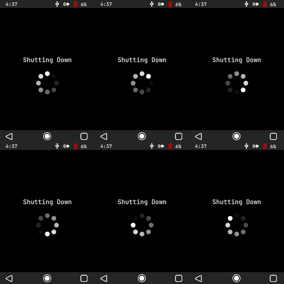
If the user holds down the power button, the system will display a shutdown animation, all peripherals will be shut off and the MCU will go into a deep sleep mode, sipping a few microamps. Whenever the user holds the power button again, the system will wake up as if the MCU was completely power cycled.
Battery Level Monitor
Reading Battery Level
The system must constantly track the battery voltage in order to avoid problems. Since batteries drain very slowly (minutes or hours), we don’t want to bog down the system by constantly polling it. Instead, we set an RTC alarm to trigger once every 10 seconds and only read the battery voltage if the alarm flag is set.
/*!
* @brief Take multiple voltage samples of the battery and return their average
* @param[in] sample_flag Flag used to trigger data sampling only when requested and not every pass of the main loop
* @return battery_level
*
* WARNING: Make sure the FPU is enabled or this will introduce large amounts of latency
* */
uint8_t
monitor_get_battery_level(uint8_t sample_flag)
{
   //Do not initialize battery level below 6, or the system will purposely shutdown on startup
   static uint8_t battery_level = 20;

   //Only sample the ADC if the sample flag is 1
   if(sample_flag)
   {
      //Disable ADC to change settings
      adc_disable();

      //Set ADC to single channel sampling
      ADC1->SQR1 &= ~(0xFF << 20);

      //Set scan order to scan PA7 (battery sense pin)
      ADC1->SQR3 &= ~0x1F; //Clear register
      ADC1->SQR3 |= (ADC_SQR3_SQ1_CHANNEL7);

      //Enable ADC after settings change
      adc_enable();

      uint16_t sample_buffer[NUMBER_OF_BATTERY_SAMPLES] = {0};

      //Take multiple different samples
      for(uint8_t current_sample = 0; current_sample < NUMBER_OF_BATTERY_SAMPLES; current_sample++)
      {
         //Start conversion
         ADC1->CR2 |= ADC_CR2_SWSTART;

         //Poll for end of conversion
         while(!((ADC1->SR & ADC_SR_EOC) >> ADC_SR_EOC_Pos));

         //Get data for channel 7
         sample_buffer[current_sample] = ADC1->DR;

         //Clear status flags
         ADC1->SR = 0;
      }

      //Disable ADC to change settings
      adc_disable();

      //Average the samples
      float average_samples = 0; //Float needed to avoid rounding errors

      for(uint8_t current_sample = 0; current_sample < NUMBER_OF_BATTERY_SAMPLES; current_sample++)
      {
         average_samples += sample_buffer[current_sample];
      }

      average_samples /= NUMBER_OF_BATTERY_SAMPLES;

      //Remap the raw ADC values to a battery percentage of 0 - 100
      battery_level = monitor_adc_to_battery_level(average_samples);
   }

   return(battery_level);
}
We’re going to read the voltage with the onboard ADC, and the function above has a lot of bit flipping to set it up correctly. To summarize, we’re going to disable the ADC, modify its settings to read off of the battery sense pin, take multiple samples, and average those samples. We now have a good estimation of the battery level, but it’s in raw 12-bit ADC values (0 – 4095), so we simply remap it to a battery percentage of 0 – 100.
Operating Voltages and Warnings
Another very important aspect of monitoring the battery voltage is safety. If our battery drains below the minimum buck-boost voltage, our system could potentially enter a dangerous in-between state. This means that perhaps there is just enough voltage to keep the MCU and/or SD card powered up but in limbo. The MCU could flail around unpredictably, toggling GPIOs and making the device do odd things.
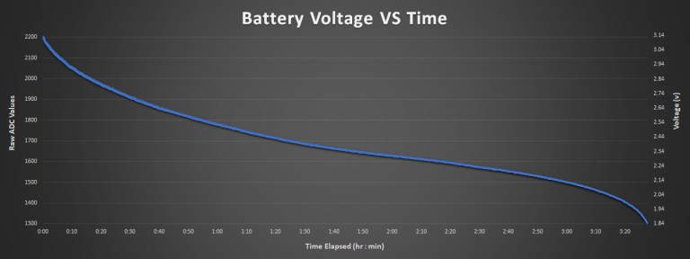
We need to know when this occurs. I wrote a logging function (for testing, not included in the main binary) that sits in the main loop and constantly monitors the battery voltage. I then let the system operate as normal and drain the batteries, while the logs were written to a block in the SD card. I did this around 10 times until I had a sizeable pool of logs to generate an average. In this manner I was able to determine that fresh batteries will sit at roughly 3.1v, and that the absolute minimum the system needs to operate is about 1.9v.
These min and max values were used to calibrate the battery percentage displayed at the top of the device’s status bar. Also, I bumped the minimum acceptable voltage up to about 2v and if the battery ever gets below 10% a warning menu is given to the user (see GUI). At 5% the system safely shuts down and forces the device into a deep sleep to avoid going into the limbo state described above.
Predicting Battery Life
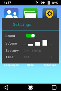
If we look back at the settings menu, we can see that it includes an estimated remaining battery life in minutes. I used the logs above to generate a lookup table, which is used in conjunction with the current battery level to estimate the remaining time before the device shuts down.
Ideally, we would want lots of data (logs while users furiously press buttons, listen to audios and are just being power hogs in general) to create an accurate model. For this simple system though, I don’t think our users will be too upset if the device only lasts 40 minutes instead of 50.
USB Sense
/*!
* @brief Get the current state of usbsense
* @param[in] NONE
* @return usb_sense Returns 2 if USB charger is plugged in, else 0. Returning 2 for TRUE
*                   saves a few instructions by not having to shift the result to the right.
*/
uint8_t
monitor_get_usb_status(void)
{
   //Read usbsense pin
   return(GPIOC->IDR & 0x02);
}
The USB sense is very basic. I ran out of external interrupt pins, so I just tied the USB power line to a 5v-tolerant GPIO that gets polled within the main system state machine. If the USB is present, no battery warnings/forced shutdowns will be given, since all system power is being provided from the plug.
PRODUCTION TESTING
The production test jig described on the Hardware page needs a corresponding set of software tests to verify that the system is running correctly. If this were a real product, such a lengthy test that required immense user interaction would be out of the question.
One of the best solutions I’ve seen for production testing is just drop shipping a raspberry pi or small PC with your test jig and having an onboard program automate as much of the physical interaction as possible.
The simple tests shown in this section would also need to be greatly expanded, but as I stated before, this is really just to show potential employers that I know how to carry out production testing.
USB
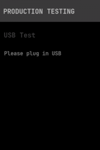
This test is extremely simple. The system just waits until it detects that the user has plugged in the USB cable.
Battery Level
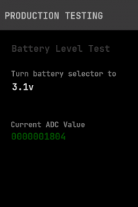
In order to make sure that the system is correctly reading battery voltage, we’re going to use the physical battery emulator on the test jig. There are five possible voltages and the test screen instructs the operator which one should be selected. The ADC is then constantly polled until it registers a battery voltage which is within a tolerance range of the current selection.
The test will not advance until the current voltage is achieved, and if this never occurs, the operator is instructed to fail the unit and log the corresponding ADC value (displayed on the screen) in the Excel test file.
Touchscreen
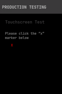
Since the touchscreen is one of the most important modules of the entire system, we need to verify that it is functioning properly. This is rather simple. A target (a red “X”) is displayed at a known location on the screen, and the user is instructed to click it. Once the system recognizes a touch has occurred within the boundaries of the target, it shifts the target to a different known location. In total this repeats itself five times, varying both X and Y axis.
If the operator can correctly hit each of the five targets the test passes, otherwise it will not advance.
Main Power Button
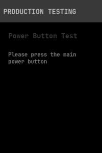
This test just waits until it registers a main power button click by the user.
Audio
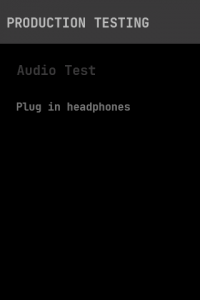
There are two sections to the audio testing. First, the system simply waits until it detects that the user has plugged in headphones into the headphone jack.
Next, a sample audio is triggered, and the operator must listen and verify that it is actually playing.

