Firmware & Software
The Embedded Resume Device would not be what it is without its solid firmware base. I decided early on that I wanted it to have a full set of features and that I was going to put in the time to make the code base shine. Nearly 13,000 lines of embedded C code written entirely by me compliment the hardware and bring out features such as audio playback, battery level monitoring, USB sense, a rich GUI and much more.
My Mission
I suppose that I could have just used CubeMX and pulled GitHub libraries to tackle most of the work, but where’s the fun in that? I wanted to show employers that I am knowledgeable and experienced in low-level firmware development, and so I made the decision to bring the system up from the bare-metal register level, through peripheral drivers, middleware and eventually a light application layer.
I did not use a single library in the process, and the only third-party code in the final binary is the vendor startup file and CMSIS core register definitions. Because of this, building the firmware codebase was by far the portion of the project which took the longest.
I spent many many nights flipping through reference manuals and staring red eyed at a debug console, but I am so glad that I decided to go this route. I hope you enjoy reading how I brought the firmware to life.
Tools & Toolchains
Embedded C
All 13,000 lines of firmware present on the Embedded Resume Device are written in bare C and are targeted toward small, embedded processors. I have been learning C (specifically embedded C) for about three years, and it is by far the programming language I am most comfortable in.
I thought about using C++, since I could have implemented the entire state machine module and GUI with a much cleaner object-oriented structure. Admittedly though, my skills with bare C are much better than with C++, and plain C is still the de facto standard for embedded systems firmware.
Integrated Development Environment (IDE)
I didn’t want to pull my own software toolchain together (compiler, linker, etc.) since I already had enough work to do as it was. I decided to go the easy route and just use an IDE. In the past, I have always been fond of Keil µVision and began firmware development there.
As the days went by and my binary grew however, I started to sweat looking at the 32KB trial code limit. In order to use the full 64KB of onboard FLASH, I decided to switch mid project to STM32CubeIDE, which has no code limit (that I know of).
If you’re an embedded firmware engineer, you’re probably staring in horror at your computer screen, since Keil µVision natively uses its ARMCC compiler for STM32s and STMCubeIDE runs off GCC. Switching compilers is generally a terrible idea, since it leads to the really really low-level bugs, timing issues and other fun problems.
After copying all my files over to STM32CubeIDE, I hit compile and…..everything worked perfectly fine. I carried out the majority of the project there with no problems.
Version Control
I used Git and GitHub to create revisions and keep track of all my changes throughout the project. This was particularly helpful whenever I accidently broke the code or created a bug and didn’t catch it until a few days later. I like using GitHub as a backup/repo host because it is immensely popular and gives me an easy way to publish my projects.
Although not mentioned on the “Hardware” page, I also used it for my KiCAD schematic capture and board layout. This helped me keep track of what hardware revisions were sent to the fabrication house and how their bugs were corrected.
Hardware Tools
Embedded systems engineers need a good set of hardware tools to help develop their firmware and verify that their PCB is working correctly.
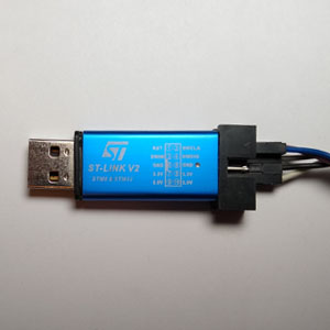
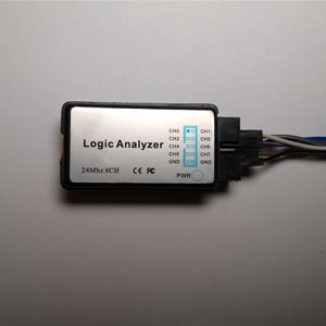
To download code to the board and perform MCU debugging, I used the ST-Link, a popular debugger/programmer that is very cost effective. During board bring up a logic analyzer is invaluable, and I used mine extensively to debug the SD card drivers.
Apart from these, I had my home lab filled with everything one would need for debugging a pesky PCB: Soldering station for jumping traces and soldering on test wires, Oscilloscope, power supplies, multimeter, USB microscope etc.
Software
Along with the IDE, there were a few other programs that I like to use while developing my systems.
- RealTerm – An open-source serial terminal that allows users to adjust advanced settings and read raw data values. I used this to talk to the Embedded Resume Device’s onboard USB-UART.
- HxD32 – A no-frills hex editor that I used to format and edit bitmap and audio files before being uploaded to the SD card.
- Pulseview – An open-source logic analyzer software that is compatible with my USB module and comes with a fairly large number of supported protocols.
System Overview
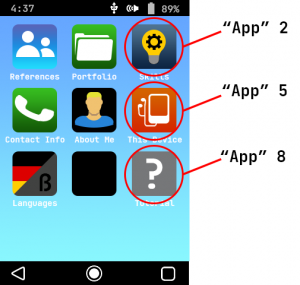
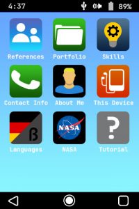
The best way for me to explain the system’s firmware architecture is to take a top down approach starting at the highest abstraction layer, the end user experience. The Embedded Resume Device looks and feels like a modern cell phone. It features a home screen with “apps” that can be selected by the user and which subsequently lead to individual menus playing graphics and audio (see GUI below).
One of the most important concepts to keep in mind is that the graphical user interface (GUI) here is not just a side module that helps the system display info related to the main thread; it is the main thread. The device acts almost like a choose-your-own-adventure PowerPoint presentation, and its only goal is to display permanent information. For this reason, the entire system is essentially just one large series of menus.
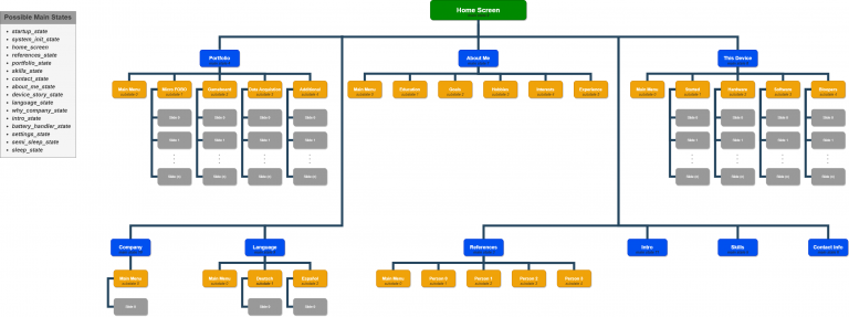
These “menus” are implemented across two levels of nested state machines. The higher level, the main system state machine, handles logic for switching between “apps” and startup and sleep states. For example, this tells the system to transition from the home screen to the Portfolio app when the user clicks on its icon.
Below this sits a parallel layer of sub state machines which are nearly independent from the main state machine and handle transition logic within each app and a few other task handlers. The user navigates through the device by transitioning between states and substates.
Home Screen App Reference
Note: The word “app” in a software context usually refers to an application running on an operating system (OS). Since each “app” for this simple system is merely a state machine, it is not a true application in the classic sense. In the context of this article, it may be helpful to think of each of these as an object containing attributes such as a home screen icon, a title, submenus, and helper functions.
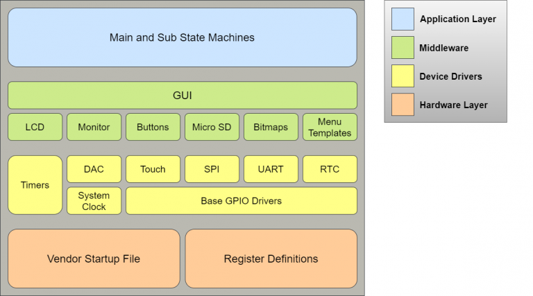
Below these high-level state machines is a fairly typical bare-metal embedded systems stackup. The base hardware layer is handled by the vendor, ST, and includes register definitions and a startup file defining things like stack size and the interrupt vector table. Above that are device drivers, which form a hardware abstraction layer (HAL) and allow other modules to interact with peripherals such as SPI and an onboard DAC. This HAL is used by middleware functions, like the Micro SD module, to build a feature-rich GUI. Finally, this GUI is used directly by the state machines mentioned above to display all of the system’s graphics and provide a rich user experience.
State Machines
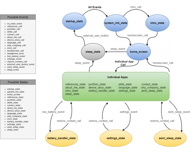
The entire firmware architecture revolves around two state machines, the main system state machine and a number of sub state machines. The diagram above helps reaffirm this point and emphasizes the fact that the user navigates around the system by transitioning through main and sub states.
Main System State Machine
The main state machine is the heart of the system and handles high-level flow control logic. It is responsible for booting the device properly and responds to events such as low battery or an external user button press.
Boot Sequence
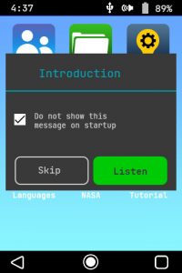
Looking at the diagram above, we see that the system enters the startup_state upon power up, a filler state that always leads to the system_init_state. This in turn, displays a boot animation and does a bit of housekeeping to ensure that the main state machine will work properly. If the user has never turned the device on before, it will transition to the intro_state, where a brief tutorial audio will be played. Finally, the system will be put into the homescreen_state, which is more or less the idle state for this state machine.
Individual Apps
From the home_screen state, the user can transition to one of nine main states (“apps”) by physically selecting its corresponding icon. For example, if I am on the home screen and I push on the “Contact Info” icon, the system will transition into the contact_state.
Each of the nine apps has its own mini, nested state machine that fires up when the main state machine transitions to its corresponding app. These nested state machines handle all functionality while the user stays inside of the same app. The most important thing to remember here is that the main system state machine does not know nor care about what the nested state machine is doing.
For example:
1. The user starts on the home screen and clicks the “Contact Info” icon
– The main system state machine transitions to the contact_state
– A sub state machine specifically for the Contact app starts up in substate_0 and displays the main Contact menu
2. The user now presses the “Deutsch” menu option
– The main state machine does not know nor care about this
– The sub state machine moves from substate_0 (Main contact menu) to substate_1 (Deutsch menu)
* At this point the main state machine only knows that it is in the contact_state and nothing else. The sub state machine only knows that it is in substate_1 and should display the Deutsch menu
Additional States
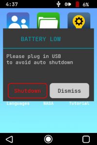
Along with the core apps, there are a few other states which help run background tasks and make sure the device runs correctly. One is the battery_handler_state which alerts the user if the battery level drops below 10% and safely shuts down the device if it is below 5% and no USB is present.
There are also the semi_sleep_state and sleep_state which respond when the user presses or holds the main power button, exactly like a cell phone. Finally, the settings_state presents the user with a pop-up menu where they can change things like volume and set the current time.
Implementation
Let’s put the diagrams aside for a second and take a look at the actual code. A standard way of implementing state machines in C is to use a series of conditional statements (switch, else if etc.). However, our system contains a fairly large number of states and events; doing things this way could lead to spaghetti code.
We’ll use another common (and in my opinion cleaner) design pattern, a table of function pointers. For this setup, we need two functions: an event handler and a state transition handler. Take a look at the code excerpts below.
/*!
* @brief This looks at all possible events in the main system state machine, ranks them in order
*        of importance, then sets the current main event to the most important.
* @param[in] NONE
* @return NONE
*
*/
void
states_update_main_event(void)
{
   //Clear the main event status to begin with
   states_set_main_event(no_main_event);

   //Check if any homescreen-related events have triggered
   states_main_event_homescreen();

   //See if any user buttons have been pressed
   states_main_event_user_buttons();

   //Check for low battery level or battery handler events
   states_main_event_battery();

   //Check if the main power button has been pressed
   states_main_event_main_power_button();
}
/*!
* @brief Uses the current main event along with the current main state to determine the next appropriate state
* @param[in] NONE
* @return NONE
*
*/
void
states_update_main_state(void)
{
   static void (*main_state_table[max_main_state][max_main_event])(void) =      //[current state][event]
   {
      /* no_event                 references_call             portfolio_call          skills_call             contact_call           about_me_call
       * device_story_call         language_call               why_company_call        intro_call              homescreen_call        headphone_error
       * low_battery               settings                    restore_context_call    external_button         semi_sleep             sleep
       */

      //Startup
      {states_system_init,       states_system_init,         states_system_init,     states_system_init,     states_system_init,    states_system_init,
       states_system_init,       states_system_init,         states_system_init,     states_system_init,     states_system_init,    states_system_init,
       states_system_init,       states_system_init,         states_system_init,     states_system_init,     states_system_init,    states_system_init},

      //System Init
      {states_app_home,          states_app_home,            states_app_home,        states_app_home,        states_app_home,       states_app_home,
       states_app_home,          states_app_home,            states_app_home,        states_app_intro,       states_app_home,       states_app_home,
       states_app_home,          states_app_home,            states_app_home,        states_app_home,        states_app_home,       states_app_home},
      //Home
      {states_app_home,          states_app_references,      states_app_portfolio,   states_app_skills,      states_app_contact,    states_app_about_me,
       states_app_device,        states_app_languages,       states_app_company,     states_app_intro,       states_app_home,       states_app_home,
       states_battery_handler,   states_settings_menu,       states_app_home,        states_semi_sleep,      states_semi_sleep,     states_sleep},

      //The rest of the table was removed on the website example for the sake of brevity
   };


   e_event_main tmp_current_event = states_get_main_event();
   e_state_main tmp_current_state = states_get_main_state();

   //Bounds check on table indices
   if((tmp_current_state < max_main_state) && (tmp_current_event < max_main_event))
   {
      main_state_table[tmp_current_state][tmp_current_event]();
   }

   //Reset event, so the same event does not trigger a transition more than once
   states_set_main_event(no_main_event);
}
In our system, these two functions are called every iteration of the main loop. states_update_main_event() carries out a series of checks to see if anything in the system (a button press, low battery etc.) has triggered an event. It moves down sequentially checking events of greater and greater importance. This ensures that the most urgent, currently active event overwrites all other, less-important events.
The states_update_main_state() is called next and contains a large 2D array of function pointers. Each of these function pointers corresponds to the appropriate function that should be called when the system is in a current state and experiences a particular event.

For example, if our system is in the home_screen state and it experiences a references_call event, the states_app_references() function will be called.
In this manner, the system can move from state to state calling the appropriate function based solely off of the current event and the current state.
Sub State Machines
Once the main state machine transitions to an app, an independent, local state machine takes care of all interactions within that specific app. Since these individual state machines are much less complex than the main state machine, they were generally implemented with simple conditional statements (switch or else if). This is much easier to grasp with an example.
/*!
* @brief This is an app consisting of past employers and their contact information
* @param[in] NONE
* @return NONE
*
*/
void
states_app_references(void)
{
   t_light_button substate0_buttons[4] =
   {
         {.major_text = "Person 1", .minor_text = "Director", .image[0] = address_buffer[person1_small_not_pressed],
          .image[1] = address_buffer[person1_small_pressed], .bmp = NULL},
         {.major_text = "Person 2", .minor_text = "Director", .image[0] = address_buffer[person2_small_not_pressed],
          .image[1] = address_buffer[person 2_small_pressed],.bmp = NULL},
         {.major_text = "Person 3", .minor_text = "Former Supervisor", .image[0] = address_buffer[person3_small_not_pressed],
          .image[1] = address_buffer[person 3_small_pressed],.bmp = NULL},
         {.major_text = "Person 4", .minor_text = "Imaging Technician", .image[0] = address_buffer[person4_small_not_pressed],
          .image[1] = address_buffer[person 4_small_pressed], .bmp = NULL},
   };


   static e_substate previous_substate = substate0 ;
   e_substate tmp_current_substate = states_get_substate();

   //Only redraw the menu if a main state transition, a substate transition or a button press has
   //occurred. Not constantly writing helps with LCD flicker.
   if((references_state != states_get_main_state()) ||
      (tmp_current_substate != previous_substate) ||
      (restore_context_call == states_get_main_event()))
   {
      switch(tmp_current_substate)
      {
      case substate0:
         gui_create_menu_type1("References", substate0_buttons, MENU1_MAX_BUTTONS, NO_BUTTON_PRESS);
         break;

      case substate1:
         {
            const t_person_profile profile_person1 =
            {.name = "Person 1", .job_title = "Director", .phone_number = "(555)-555-555",
             .email = "Example@csulb.edu", .profile_image = address_buffer[person1_large]};

            gui_create_menu_type2(profile_person1);
            break;
         }

      case substate2:
         {
            const t_person_profile profile_person2 =
            {.name = "Person 2", .job_title = "Director", .phone_number = "(555)-555-555",
             .email = "example@csulb.edu", .profile_image = address_buffer[person2_large]};

            gui_create_menu_type2(profile_person2);
            break;
         }

      case substate3:
         {
            const t_person_profile profile_person3 =
            {.name = "Person 3", .job_title = "Former Supervisor", .phone_number = "(555)-555-555",
             .email = "example@csulb.edu", .profile_image = address_buffer[person3_large]};

            gui_create_menu_type2(profile_person3);
            break;
         }

      case substate4:
         {
            const t_person_profile profile_person4 =
            {.name = "Person 3", .job_title = "Former Supervisor", .phone_number = "(555)-555-555",
             .email = "example@csulb.edu", .profile_image = address_buffer[person4_large]};

            gui_create_menu_type2(profile_person4);
            break;
         }

      default:
         break;
      }

   }


   if(references_state == states_get_main_state())
   {
      gui_update_menu1_buttons(substate0_buttons, substate0);
   }

   previous_substate = states_get_substate();
   states_references_substate_handler();
   states_set_main_state(references_state);

}
Above we can see the main function for the References app. Upon first entry the app’s sub state is substate_0, and a switch statement is used to determine that the main References menu should be displayed. It then calls a specific sub state handler function.
/*!* @brief Uses the current substate and button information to transition to
*        the correct next substate. This allows the user to navigate through the
*        References app's menus
* @param[in] NONE
* @return NONE
*
*/
void
states_references_substate_handler(void)
{

   if(references_state == states_get_main_state())
   {
      uint8_t active_button = buttons_status(menu1_template,(sizeof(menu1_template) / sizeof(*menu1_template)));
      e_substate tmp_current_substate = states_get_substate();

      //Only substate 0 (The main list) has interactive buttons
      if((substate0 == tmp_current_substate) && (NO_BUTTON_PRESS != active_button))
      {
         static const e_substate transition_table[] ={substate1, substate2, substate3, substate4};
         states_set_substate(transition_table[active_button]);
      }

      //If the back button was pressed, decrease and go back to the main list
      else
      {
         active_button = buttons_status(user_button_template,(sizeof(user_button_template) / sizeof(*user_button_template)));

         if(back_button == active_button)
         {
            states_set_substate(substate0);
         }
      }
   }
}
states_references_substate_handler() is the heart of the local state machine and is solely responsible for determining transitions between sub states. Above we can see that it checks which sub state it is currently in, poles the appropriate set of menu buttons, then decides if the sub state needs to be changed.
Although this is one of the simplest apps in the system, the concept is the same for all of them. Each app function has a set of sub state handlers that determine transitions and tell the app function what to display.
Graphical User Interface
Types of Menus
Menu Type 1:
Icon List
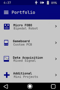
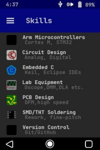
One of the most common types of menus on the Embedded Resume Device is the icon list. This is a general-purpose menu that consists of a simple list of options from which the user can choose. These can be anything from my portfolio projects to past employers that I am providing as job references.
Each option has a brief two-line summary that helps the user determine what they are selecting, as well as either a thumbnail picture or a bitmap. There is nothing too fancy here, it just serves as a way to access sub elements within an app.
From the code below, we can see that the menu is created more or less by displaying a series of buttons which contain attributes like text and bitmaps/images. Although not listed here, there is also a button handler which darkens a menu option and plays a click audio if it is pressed.
/*!
* @brief Display a selection list type menu on the LCD
* @param[in] title The menu title that will be displayed below the status bar
* @param[in] button_list Contains the list of menu options and their attributes
* @param[in] list_length Variable to keep track of array length since passing by pointer loses this info
* @param[in] active_button If one of the menu options has been pressed by the user, this variable
*                          tells the function to make it appear different
* @return  NONE
*
* NOTE: This function has a few "magic numbers", aka seemingly random numbers
*       without explanation. These are offsets to position each section of the menu
*       correctly and were created by trial and error and tuned with a visual check.
*       By defining most of these numbers in variables, the function trades speed
*       for coding clarity and readability.
*/
void
gui_create_menu_type1(char *title, t_light_button *button_list, size_t list_length, uint8_t active_button)
{
   gui_set_footer_color(BLACK);
   gui_set_status_bar_color(GUI_HEADER_DARK);

   gui_create_title_bar(title);

   //Text and picture/bitmap
   for(uint8_t current_button = 0; current_button < list_length; current_button++)
   {

      //Button background
      uint16_t y_initial = menu1_template[current_button].y_position;
      uint16_t y_final = y_initial + menu1_template[current_button].height;
      lcd_draw_rectangle(THEME_NEAR_WHITE, 0, y_initial, 320, y_final);

      //Display button picture
      uint16_t offset_x = MENU1_PICTURE_X_OFFSET;
      uint16_t offset_y = ((current_button*MENU1_BUTTON_SPACING) + HEADER_OFFSET + 9); //9 pixels down from the bottom of the header
      uint32_t image_address = button_list[current_button].image[0];
      const uint8_t *p_tmp_bmp = button_list[current_button].bmp;

      if(image_address != null_address)
      {
         lcd_image_from_sd(offset_x, offset_y, offset_x + MENU1_PICTURE_WIDTH, offset_y + MENU1_PICTURE_HEIGHT, image_address);
         offset_x += 80; //Move text far from the left screen, since pictures are big
         offset_y =  MENU1_TEXT_Y_OFFSET + (current_button*MENU1_BUTTON_SPACING) + SB_OFFSET;
      }

      else if (NULL != p_tmp_bmp)
      {
         //If there is no picture, display the button bitmap
         offset_x = MENU1_BMP_X_OFFSET;
         offset_y += 18;
         lcd_send_bitmap(button_list[current_button].bmp, offset_x, offset_y, BLUE_PURE, THEME_NEAR_WHITE);
         offset_x += 60; //Move text a medium amount from the left, since bitmaps are smaller than pictures
      }

      else
      {
         //If there is neither a picture nor a bitmap, shift the text down from the header
         offset_y += 18;
      }

      //Display major text
      lcd_print_string_small(button_list[current_button].major_text, offset_x, offset_y, THEME_TEXT, THEME_NEAR_WHITE);

      //Display minor text
      offset_x += 2;
      offset_y += 21;
      lcd_print_string_small(button_list[current_button].minor_text, offset_x, offset_y, THEME_SUBTEXT, THEME_NEAR_WHITE);

      //Display menu arrows
      offset_x = MENU1_ARROWS_X_OFFSET;
      offset_y =   MENU1_ARROWS_Y_OFFSET + (current_button*MENU1_BUTTON_SPACING) + SB_OFFSET;
      lcd_send_bitmap(menu_arrow_bmp, offset_x, offset_y, THEME_TEXT, THEME_NEAR_WHITE);
   }

}
Menu Type 2:
Personal Profile
Inside of the “References” app, users can choose from four of my past employers that I am using as references. Once selected, the system will enter a personal profile menu that displays things like a professional profile picture, their title and company, and a phone number and/or email to be contacted at.
Although I would most likely receive an outstanding review from my friend’s dog Maggie (right), this is simply the result of removing all personal data and replacing it with an example.
Looking at the code, not much is different from a menu type 1. The main diversion is the use of a large profile picture which is pulled from the SD card and displayed above the menu list.
/*!
* @brief Display a personal profile similar to a cell phone's "contacts" menu
* @param[in] tmp_profile A structure providing the attributes of a given person
* @return  NONE
*/
void
gui_create_menu_type2(const t_person_profile tmp_profile)
{
   gui_set_footer_color(BLACK);
   gui_set_status_bar_color(GUI_HEADER_DARK);
   gui_create_title_bar("Profile");

   //Large profile picture.NOTE: All profile pictures have the dimensions 320 x 164
   lcd_image_from_sd(0, HEADER_OFFSET, 320, HEADER_OFFSET + MENU2_PICTURE_HEIGHT, tmp_profile.profile_image);
   lcd_print_string(tmp_profile.name, MENU2_NAME_X_OFFSET, MENU2_NAME_Y_OFFSET, THEME_NEAR_WHITE, GRAY_DARK);

   //Gray background for menu text
   lcd_draw_rectangle(THEME_NEAR_WHITE, 0, HEADER_OFFSET + MENU2_PICTURE_HEIGHT, 320, FOOTER_OFFSET);

   //Display main text
   uint16_t x_offset = 60;
   uint16_t y_offset = HEADER_OFFSET + MENU2_PICTURE_HEIGHT + MENU2_TEXT_OFFSET;
   lcd_print_string_small(tmp_profile.job_title, x_offset, y_offset, THEME_TEXT, THEME_NEAR_WHITE);
   y_offset += MENU2_TEXT_SPACING;
   lcd_print_string_small(tmp_profile.phone_number, x_offset, y_offset, THEME_TEXT, THEME_NEAR_WHITE);
   y_offset += MENU2_TEXT_SPACING;
   lcd_print_string_small(tmp_profile.email, x_offset, y_offset, THEME_TEXT, THEME_NEAR_WHITE);

   //Display subtext
   x_offset += 5;
   y_offset = HEADER_OFFSET + MENU2_PICTURE_HEIGHT + MENU2_SUBTEXT_OFFSET;
   lcd_print_string_small("CSULB", x_offset, y_offset, THEME_SUBTEXT, THEME_NEAR_WHITE);
   y_offset += MENU2_TEXT_SPACING;
   lcd_print_string_small("Mobile", x_offset, y_offset, THEME_SUBTEXT, THEME_NEAR_WHITE);
   y_offset += MENU2_TEXT_SPACING;
   lcd_print_string_small("Work", x_offset, y_offset, THEME_SUBTEXT, THEME_NEAR_WHITE);

   //Display bitmaps
   x_offset = 6;
   y_offset = HEADER_OFFSET + MENU2_PICTURE_HEIGHT + MENU2_TEXT_OFFSET;

   lcd_send_bitmap(job_icon_bmp, x_offset, y_offset, THEME_MAIN, THEME_NEAR_WHITE);
   y_offset += MENU2_TEXT_SPACING;
   lcd_send_bitmap(phone_icon_bmp, x_offset, y_offset, GREEN_PHONE, THEME_NEAR_WHITE);
   y_offset += MENU2_TEXT_SPACING;
   lcd_send_bitmap(mail_icon_bmp, x_offset, y_offset, RED_DARK, THEME_NEAR_WHITE);
}
Menu Type 3:
Slide Show
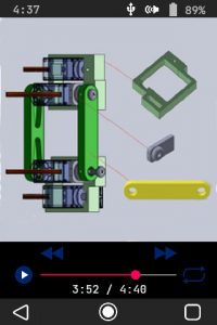
The previous two menus were interesting, but now we’re going to spice this GUI up a bit. The type 3 menu is the most complicated in the system and incorporates audio, images, buttons, and more. It consists of a series of visual slides and is generally used to showcase pictures of my previous projects.
Unlike a typical PowerPoint however, each slide has an accompanying audio of me explaining the image. For example, the “Data Acquisition” project of the “Portfolio” app, consists of schematic capture screenshots and prototype images and is complimented by a recording of me describing how the circuit functions.
/*!
* @brief Display a slide show consisting of either voice clips with pictures or voice clips with text
* @param[in] NONE
* @return  NONE
*/
void
gui_create_menu_type3(void)
{
   gui_set_footer_color(GRAY_MENU3);
   gui_set_status_bar_color(GRAY_MENU3);

   //If nothing else has triggered this function, it was a main or substate change or a slide change,
   //and the entire menu will need to be redrawn
   lcd_draw_rectangle(BLACK, 0, MENU3_UTILITIES_BAR_OFFSET, 320, FOOTER_OFFSET);

   for(e_menu3_button current_button = menu3_left_arrow; current_button < menu3_time_bar0; current_button++)
   {
      uint16_t x = menu3_template[current_button].x_position;
      uint16_t y = menu3_template[current_button].y_position;
      lcd_send_bitmap(menu3_template[current_button].bmp, x, y, THEME_MAIN, BLACK);
   }

   //Set the initial audio play button visual to "play" aka a triangle inside of a circle
   lcd_send_bitmap(play_button_inner_symbol, MENU3_PLAY_BUTTON_ICON_X_OFFSET, MENU3_PLAY_BUTTON_ICON_Y_OFFSET, WHITE_PURE, THEME_MAIN);
}
Above, we can see that creating the initial menu is straightforward, since it’s mostly just making a background and displaying a few bitmaps. The complicated portion is keeping track of all the visual elements and button presses. The user has a variety of options including moving between slides, playing/pausing audio, and resetting the audio. This is all handled within a specific button handler.
There is also a timer bar which keeps track of the current audio play time. It is fed from a timer that is piggybacking off the DAC’s clock. Put simply, whenever the clock that feeds the DMA (and therefore the DAC audio) is turned on, it is used as the source for a second timer with a much higher prescaler. The GUI’s timer bar can tell how much time has passed by reading the current value of this timer.
App-Specific Menus
Along with the general-purpose menus which are meant to be reused, there are also a few stand-alone implementations. These are usually so unique that they cannot be utilized for other apps and had to be created individually.
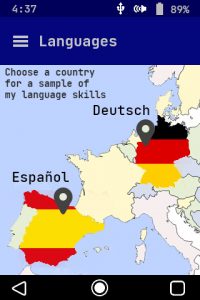
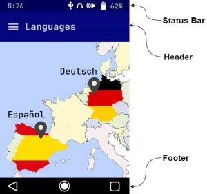
Although these are not meant to be portable, they share many of the common features of the other menu types, generally revolving around displaying buttons and images. Note: The base image for the “Languages” menu was taken from https://d-maps.com/m/europa/europemax/europemax34.svg and further altered in photoshop.
Pop-Up Menus
Pop-up menus are a bit of an oddball compared to the rest of the system. They are small and cover only a portion of the screen, displaying things like warnings. Let’s first look at how they are created.
/*!
* @brief Displays a pop-up warning message to the user
* @param[in] tmp_buttons List of maximum two buttons to display as options
* @param[in] strings Text to display on the menu as well as inside the buttons
* @return NONE
*
* NOTE: strings should be in the following form
*      char *example[5] = { "left button text", "right button text",
*                           "main warning text", "minor text line 0", "minor text line 1"};
*
*/
void
gui_create_warning_menu( t_button *tmp_buttons, char **strings)
{
   //Background. This starts at x = 10 and ends at x = 310 aka 10 pixels offset from the edges
   lcd_draw_rectangle(GRAY_MEDIUM_DARK, 10, MENU_WARNING_BACKGROUND_OFFSET, 310, MENU_WARNING_BACKGROUND_HEIGHT);

   uint16_t y_offset = MENU_WARNING_BACKGROUND_OFFSET + 25;

   //Main warning text
   lcd_print_string(strings[2], 70, y_offset, BLUE_SKY, GRAY_MEDIUM_DARK);

   //Line dividing major text and the rest of the menu
   y_offset += 40;
   lcd_draw_rectangle(BLUE_SKY, 10, y_offset, 310, y_offset + 2);

   //Minor text
   y_offset += 20;
   lcd_print_string_small(strings[3], 20, y_offset, THEME_LIGHT_GRAY, GRAY_MEDIUM_DARK);
   y_offset += 20;
   lcd_print_string_small(strings[4], 20, y_offset, THEME_LIGHT_GRAY, GRAY_MEDIUM_DARK);

   buttons_create(tmp_buttons, strings, 2); //There are ever only 2 buttons in this menu
}
Looking at the code above, we can see they’re fairly simple and consist mainly of informative text and two option buttons; nothing to write home about.
The hard part is getting these menus to play nice with the rest of the system. By their very nature, pop-up menus can potentially appear at any point while the device is functioning, which throws a wrench in our nice, organized system state machine.
Say, for example, we are in the “Portfolio” menu looking at a slide when a low battery event occurs. We would expect a low battery warning menu to pop up and, when cleared, return us to the exact same slide we were previously viewing. How do we safely display a pop-up menu without breaking the system?
/*!
* @brief Pushes or pops the current/previous state, substate, slide
* @param[in] action_select Either CONTEXT_PUSH or CONTEXT_POP, used to determine how the function should respond
* @return  previous_context Previous system context upon entering a given function
*/
void
states_previous_context(uint8_t action_select)
{
   static uint32_t context[3] = {0};

   if(CONTEXT_PUSH == action_select)
   {
      context[0] = states_get_main_state();            // Main state
      context[1] = states_get_substate();              // Substate
      context[2] = states_get_current_slide_number();  // Slide
   }

   else if (CONTEXT_POP == action_select)
   {
      states_set_main_state(context[0]);            // Main state
      states_set_substate(context[1]);              // Substate
      states_set_current_slide_number(context[2]);  // Slide
   }

   else
   {
      uart1_printf("\n \r WARNING states_previous_context() called with illegal request\0");
   }

}
When most modern microcontrollers call a function, they save the context of all general-purpose registers on the stack before transitioning. We’re going to use the exact same technique here. Before calling the battery handler function in the example above, our system saves exactly where it is. This includes the current state, substate, and slide.
You may have noticed that there is a main system event in the state machine module called restore_context_call. This is used in conjunction with the function above to return the system to whichever menu state it was in before the pop-up menu occurred. By either “pushing” or “popping” the values inside this function, the system will be able to reliably enter and exit pop-up menus.
Settings Menu
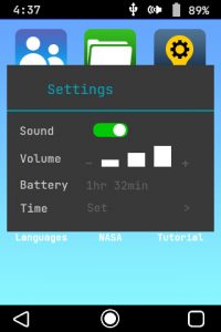
The settings menu is technically still a pop-up, but it’s complicated enough to warrant its own section. All the fundamentals still apply from the section above regarding saving/restoring context and the actual size of the menu. The difference comes in the large number of buttons and features built into the settings menu.
Above we can see that the user is able to toggle audio, change volume, and see the estimated remaining battery life (in minutes). Each of these features is implemented through helper functions that take care of receiving and sending data to their respective modules.
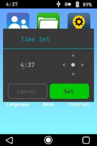
There is also an option to set the current time to be displayed on the status bar (fed by the RTC), which is done through a separate submenu.
/*!
* @brief Displays a menu for users to change basic device settings
* @param[in] NONE
* @return NONE
*
*/
void
gui_create_settings_menu(void)
{
   //Background. This starts at x = 10 and ends at x = 310 aka 10 pixels offset from the edges
   lcd_draw_rectangle(GRAY_MEDIUM_DARK, 10, MENU_WARNING_BACKGROUND_OFFSET, 310, MENU_WARNING_BACKGROUND_HEIGHT);

   //Main warning text
   uint16_t y_offset = MENU_WARNING_BACKGROUND_OFFSET + 25;
   uint16_t x_offset = 70;
   lcd_print_string("Settings", x_offset, y_offset, BLUE_SKY, GRAY_MEDIUM_DARK);

   //Line dividing major text and the rest of the menu
   x_offset = 10;
   y_offset += 40;
   lcd_draw_rectangle(BLUE_SKY, 10, y_offset, 310, y_offset + 2);

   //Minor text
   x_offset += 20;
   y_offset += 20;
   lcd_print_string_small("Sound", x_offset, y_offset, WHITE_PURE, GRAY_MEDIUM_DARK);

   //Toggle button
   y_offset += 40;
   lcd_print_string_small("Volume", x_offset, y_offset, WHITE_PURE, GRAY_MEDIUM_DARK);
   lcd_print_string_small("-            +", x_offset + 110, y_offset + 5, GRAY_MEDIUM, GRAY_MEDIUM_DARK);
   gui_settings_menu_update_volume();

   y_offset += 40;
   lcd_print_string_small("Battery", x_offset, y_offset, WHITE_PURE, GRAY_MEDIUM_DARK);
   gui_settings_menu_update_battery();

   y_offset += 40;
   lcd_print_string_small("Time", x_offset, y_offset, WHITE_PURE, GRAY_MEDIUM_DARK);
   lcd_print_string_small("Set          >", MENU_SETTINGS_BUTTON_X_OFFSET, y_offset + 2, GRAY_MEDIUM, GRAY_MEDIUM_DARK);

}
Animations
To make the device feel like a real cell phone, I included some simple yet attractive animations. One key feature that helps this is the boot up sequence, which appears whenever the device is powered on from deep sleep. It consists of a series of bitmaps pulled from the SD card and really adds a bit of pizzazz to the whole device.
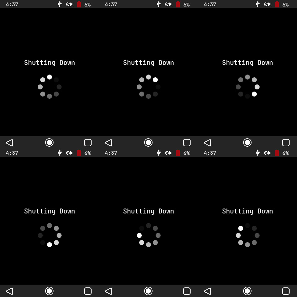
There are also smaller implementations, such as a simple spinning wheel that appears for roughly a second before the device shuts down into deep sleep. Unlike an actual phone whose OS is doing lots of background bookkeeping during this time, the Embedded Resume Device is literally only displaying the animation. In fact, if it wanted to, it could probably shut down in a few microseconds, but boy does that loading wheel look snazzy.
Status Bar, Header, and Footer
Status Bar
The status bar is a thin strip in the uppermost portion of the device’s screen and is always present. Its main job is to give the user information about how the device and the system are functioning.
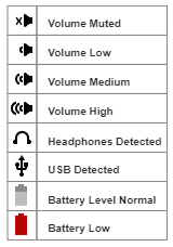
Looking at the diagram to the right, we can see that there are a variety of symbols which can appear on the status bar. These tell the user things like when the USB or headphones are plugged in as well as the current volume level.
Along with the symbols is the current time, which runs off the RTC and can be set through the settings menu.
/*!
* @brief Redraw the status bar in order to match the current menu
* @param[in] NONE
* @return  NONE
*/
void
gui_update_status_bar(void)
{
   static uint16_t previous_background_color = NULL_COLOR;
   uint16_t current_background_color = gui_get_status_bar_color();
   uint8_t background_color_change_flag = 0;

   //If the status bar has changed color, it needs to be redrawn
   if(previous_background_color != current_background_color)
   {
      lcd_draw_rectangle(current_background_color, 0, 0, 320, SB_OFFSET);
      background_color_change_flag = 1;
   }

   previous_background_color = current_background_color;

   //Update each icon
   gui_update_status_bar_battery(background_color_change_flag);
   gui_update_status_bar_volume(background_color_change_flag);
   gui_update_status_bar_time(background_color_change_flag);
   gui_update_status_bar_headphones(background_color_change_flag);
   gui_update_status_bar_usb(background_color_change_flag);

}
Another nifty feature is that the status bar dynamically changes color, meaning that if the system transitions from the homescreen to the “Portfolio” menu, the color will change from black to a dark blue. This allows us to create more aesthetically pleasing menus.
Header
The header is a large block that appears below the status bar on some menus. Its only real goal is to provide a title to the current screen and give the GUI a bit more flare.
Footer
The footer, as its name suggests, sits at the very bottom of the screen and houses the main virtual buttons. These are used much like a modern cell phone, and the user is able to do things like go directly to the home screen, navigate back one step from their current menu, and open the settings pop-up menu.
Like the header, the footer is also able to dynamically change its color to better match the current menu’s color scheme.
Home Screen Icons
Each of the apps on the system is represented on the home screen by an icon. These were created from scratch by me in photoshop, a feat I am fairly proud of considering I have difficulty drawing a stick figure sometimes.
This section proved surprisingly difficult due to the abstract nature of some of the apps. For example, how does one represent the word “skills” with a drawing? A light bulb with a gear cog? Sure, why not. I got some inspiration by googling different common bitmaps, but at the end of the day there are only so many ways to, for example, represent contact info.

Buttons
typedef struct t_button_tag
{
   uint16_t width; //In pixels
   uint16_t height;
   uint16_t x_position;
   uint16_t y_position;
   uint16_t background_color;
   uint16_t body_color;
   uint16_t text_color;
   e_button_type type;
   const uint8_t *bmp;

} t_button;
enum e_button_type_tag
{
   button_rectangle,
   button_rounded_corners,
   button_ghost

} e_button_type;


Virtual buttons are the heart of the GUI and allow the user to navigate through the system’s menus. It is important to note that when I refer to buttons here, I am talking about pixels on the LCD screen and not the physical button on the PCB.
In our system, buttons are represented as structures which have attributes like height, position, an optional bitmap and more. The user is free to define whichever combination of background, body, and text colors they like. There are three main types: the typical rectangle, a slightly more appealing version with rounded corners, and ghost type.
Both ghost and rounded buttons have curved edges which would (should) typically be implemented with vectors. I cheated and just used a five-pixel roundover bitmap, which is just fine for our simple system.
/*!
* @brief Loop through a set of given virtual buttons and display them on the
*        LCD using their individual attributes
* @param[in] buttons Array of button structures to be created
* @param[in] button_text An array of strings to be displayed inside each button
* @param[in] list_length Housekeeping variable to keep track of the array length
*                        as it is passed by pointer
* @return  NONE
*/
void
buttons_create(t_button buttons[], char **button_text, size_t list_length)
{
   //Loop through all buttons in the list
   for(uint8_t current_button = 0; current_button < list_length; current_button++)
   {
      e_button_type type = buttons[current_button].type;

      switch(type)
      {
      case button_rectangle:
         buttons_make_rectangle_button(buttons[current_button], button_text[current_button]);
         break;
      case button_rounded_corners:
         buttons_make_rounded_button(buttons[current_button], button_text[current_button]);
         break;
      case button_ghost:
         buttons_make_ghost_button(buttons[current_button], button_text[current_button]);
         break;
      default:
         break;

      }
   }
}
lcd
The Embedded Resume Device uses the QD3502 LCD from QD-Tech. I chose this in part because it has a built in ILI9486 LCD controller, which makes our lives as firmware engineers drastically easier. It has its own built in GRAM buffer and logic to support various configuration and display commands. We need to write a module that lets our MCU bring out its functionality.
Initialization
In order to use the LCD, we’re going to have to complete a series of steps upon power up. Keep in mind that all communication is actually going to the ILI9486 not the LCD directly. The datasheet provides a very well-documented section on how to go through initialization, but the main idea is that we’re going to send a list of commands that tell the LCD how we want it to operate.
/*!
* @brief Initializes LCD with system default parameters
* @param[in] NONE
* @return NONE
*/
void
lcd_init(void)
{
   //Initialize control and data lines
   lcd_gpio_init();

   lcd_reset();
   gpio_clear(LCD_CS); //Enable LCD

   //Setup base LCD register values
   //many of these are present in vendor startup code
   lcd_color_correction_set();
   lcd_power_mode_set();
   lcd_frame_rate_set();
   lcd_inversion_control_set();
   lcd_display_function_control_set();
   lcd_entry_mode_set();
   lcd_gamma_control_set();
   lcd_memory_access_control_set();
   lcd_pixel_format_set();

   // Turn off sleep mode
   lcd_send_command(LCD_CMD_SLEEP_OUT);
   timers_delay(120);

   // Start displaying contents of LCD GRAM
   lcd_send_command(LCD_CMD_DISPLAY_ON);

   // Minimum 5ms delay after on command.
   // With system clock = 100MHz, timers_delay(400) is more than acceptable
   timers_delay(400);
}
The code above initializes the MCU’s GPIO control lines, resets the LCD, feeds it a series of configuration settings, then brings it out of sleep mode. After this step, it is ready to be used by the system.
Graphics
Polygons
One of the simplest form of graphics is drawing polygons. Specifically, we want to draw rectangles in order to display menu options and other straight features.
/*!
* @brief Draws a filled rectangle on screen of a specific color
* @param[in] color A 16-bit 5-6-5 RGB color
* @param[in] x_in Initial X position
* @param[in] y_in Initial Y position
* @param[in] x_fin Final X position
* @param[in] y_fin Final Y position
* @return NONE
*/
void
lcd_draw_rectangle(uint16_t color,uint16_t x_in ,uint16_t y_in,uint16_t x_fin ,uint16_t y_fin)
{

   //Select LCD
   gpio_clear(LCD_CS);

   //Define the window the of the LCD to be written to
   lcd_set_window_address(x_in, y_in, x_fin-1, y_fin-1);

   //Put LCD in data mode
   gpio_set(LCD_RS);

   //Loop through each row and column, filling each pixel with color
   for(uint32_t row = y_in; row < y_fin; row++)
   {
      for(uint32_t column = x_in; column < x_fin; column++)
      {
         GPIOB->BSRR = 0xFFFF0000; //Clear the LCD data bus
         GPIOB->BSRR = (color >> 8); //write most significant byte
         GPIOA->BSRR = 0x00000100; //Set LCD_WR, clocking the bus data into the LCD
         GPIOA->BSRR = 0x01000000; //Clear LCD_WR

         GPIOB->BSRR = 0xFFFF0000; //Clear the LCD data bus
         GPIOB->BSRR = (color & 0x00FF); //write least significant byte
         GPIOA->BSRR = 0x00000100; //Set LCD_WR, clocking the bus data into the LCD
         GPIOA->BSRR = 0x01000000; //Clear LCD_WR
      }
   }

  gpio_set(LCD_CS);

}
The code above creates a filled rectangle of any 16-bit color anywhere on the LCD screen. It starts off by physically toggling control lines and defining a window on the screen. If we think of an LCD as an X-Y grid of pixels, this “window” is simply saying, “hey, I’m going to draw on the screen and I only want to write from rows A to B and columns C to D.”
This window is the exact size of our desired rectangle, and once it has been defined, we only need to fill it with color. Since the color is 16 bits and we only have an 8-bit bus, we’re going to need to send two separate bytes. The first (color >> 8) is simply the most significant byte, while the second is the least significant byte. By repeating this for every pixel in the window, we can create a simple rectangle.
Images
Displaying images on the screen is a bit more complicated and comes with its own challenges. The first problem is the orientation of the original file. For this system, all images stored on the SD card are 24-bit bitmaps. This format stores the file backwards and reversed, meaning that the first byte of image data is actually the bottom right corner.
Our LCD is expecting pixel data starting from the top left. We could theoretically just write firmware to flip the image on the fly, but with our tiny MCU that would make images load extremely slowly. Instead, we simply make sure that we preformat all the images on the SD card to take the burden off the STM32.
Another huge problem is that our LCD wants 16-bit color data, but our bitmaps are stored in 24 bits. Since 16-bit is not a common format, I could not find a file converter for it. I suppose I could have written a script to do the job, but that would have been an endeavor. Instead, we’re going to shift all the data coming from the SD card to force it into 16 bits.
In 24-bit color red, green, and blue are each represented with a single byte. To convert this, the most significant nibbles (green actually uses 5 bits) of each byte is removed and squeezed into 16 bits. The other real kicker is that we only have an 8-bit parallel bus, meaning that the color value will need to be split in half and sent one byte at a time.
Let’s take a look at the actual code.
/*!
* @brief Sends image from SD card to LCD
* @param[in] x_in Initial X position
* @param[in] y_in Initial Y position
* @param[in] x_fin Final X position
* @param[in] y_fin Final Y position
* @param[in] memory_starting_address Memory block location of the image on the SD card
* @return NONE
*
* NOTE: This function appears long and unruly due to the fact that many intermediate
*       functions were unrolled and optimization for speed was performed
*/
void
lcd_image_from_sd(uint16_t x_in ,uint16_t y_in,uint16_t x_fin ,uint16_t y_fin, uint32_t memory_starting_address)
{
   uint32_t total_blocks = 0, total_bytes = 0;

   //Formula: total-bytes = ((total-pixels) x (3 bytes-per-pixel))
   total_bytes = ((x_fin - x_in) * (y_fin - y_in) * 3);

   //512 bytes-per-block
   total_blocks = (total_bytes / 512);

   //Select LCD
   gpio_clear(LCD_CS);

   //Set upper left corner of image as starting address
   lcd_set_window_address(x_in, y_in, x_fin - 1, y_fin - 1);

   //Put LCD in data mode
   gpio_set(LCD_RS); //LCD_RS=1;

   //Start reading the image from the SD card
   sd_read_multiple_block(memory_starting_address);

   //Burn through the header to get to the image, starts at 0x36 offset
   uint32_t current_byte = 512;
   current_byte -= lcd_skip_bmp_header();

   uint32_t color_buffer[6] = {0}; // blue green red blue green red
   uint32_t color_number = 0;

   for(uint32_t block_number = total_blocks; block_number != 0; --block_number)
   {

      while(0 != current_byte)
      {
         /* This is just spi_receive_byte(0xFF) unrolled */
         //Send dummy byte byte
         SPI2->DR = 0xFF;

         // Wait for the receive register to fill
         while(!(SPI2->SR & SPI_SR_RXNE)){}

         color_buffer[color_number] = (SPI2->DR);
         color_number++;

         if(6 == color_number)
         {
            //First Pixel
            GPIOB->BSRR = 0xFFFF0000; //Clear data bus
            GPIOB->BSRR = ((color_buffer[2] & 0xF8) | (color_buffer[1] >> 5)); //byte_high;
            GPIOA->BSRR = 0x00000100;//Set LCD_WR
            GPIOA->BSRR = 0x01000000; //Clear LCD_WR

            GPIOB->BSRR = 0xFFFF0000; //Clear data bus
            GPIOB->BSRR = (((color_buffer[1] & 0x1C) << 3) | (color_buffer[0] >> 3)); //byte_low;
            GPIOA->BSRR = 0x00000100;//Set LCD_WR
            GPIOA->BSRR = 0x01000000; //Clear LCD_WR

            //Second Pixel
            GPIOB->BSRR = 0xFFFF0000; //Clear data bus
            GPIOB->BSRR = ((color_buffer[5] & 0xF8) | (color_buffer[4] >> 5)); //byte_high;
            GPIOA->BSRR = 0x00000100;//Set LCD_WR
            GPIOA->BSRR = 0x01000000; ////Clear LCD_WR

            GPIOB->BSRR = 0xFFFF0000; //Clear data bus
            GPIOB->BSRR = (((color_buffer[4] & 0x1C) << 3) | (color_buffer[3] >> 3)); //byte_low;
            GPIOA->BSRR = 0x00000100;//Set LCD_WR
            GPIOA->BSRR = 0x01000000; ////Clear LCD_WR

            color_number = 0;
         }

         current_byte--;

      }

      current_byte = 512;

      //Burn through the CRC bits and wait until SD card sends data valid token
      spi_receive_byte(0xFF);
      spi_receive_byte(0xFF);
      while(SD_CMD17_TOKEN != spi_receive_byte(0xFF)) {} //CMD17 token is the same as CMD18, 0xFE
   }

   //The sd card must return an entire block. Flush the unused bytes from the last block
   sd_stop_transmission();
}
This function starts off by setting the window and configuring the control lines for the LCD. It then passes the SD card the address of the image we want to display and tells it to keep sending us image data until we stop it. We skip the built-in header of the bitmap file to get to the raw image data.
Here is where we use the color conversion method described above. The main for() loop continually pulls image data from the SD Card. After it has retrieved 6 bytes (two pixels worth of 24-bit data) it converts to 16-bit color and sends each byte over the parallel bus. It does this repeatedly until the total file has been sent, at which point it flushes the rest of the unused block and tells the SD card to stop.
If at first this function looks large and unruly, that’s because well, it is. Part of the reason behind this is that we want it to run as fast as possible and it has been optimized for speed. This means that loops were unrolled (two pixels sent at a time), the contents of sub functions were spliced in, and our for() loops decrement to zero, which is less costly at the assembly level.
It would also be good to mention that the file size is set by the current window, not the bitmap itself. This is done so the GUI can display some interesting effects, but if this needed to be portable, a better solution would be to simply read the built-in bitmap header.
Fonts and Bitmaps
Although the font and bitmap display functions are inside of lcd.c, they were complex enough to warrant their own section in this article.
Bitmaps
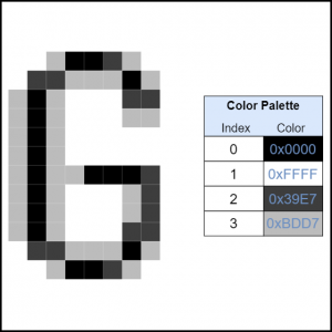
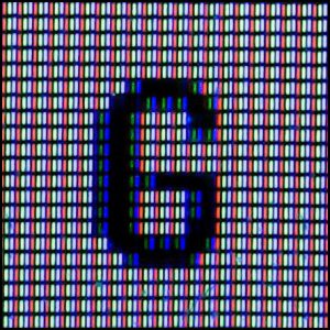
Even though I made a distinction in the title, all fonts in this system are just bitmaps, and both are displayed using exactly the same method. Most fonts for simple LCD displays are monochrome, meaning they only consist of either on (usually black) or off (usually white) pixels. Take a look at the example font below that I designed for my Electronic Gameboard project. It gets the job done; you can still tell it’s the letter “G”, but boy is it ugly.
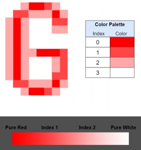
To make our device look more appealing, we’re going to design an anti-aliased font. This is fancy way of saying that each pixel can have one of four values, not only “on” or “off”. Looking at the picture above, we can see that the font for the Embedded Resume Device has a much smoother version of the same letter. (It looks pretty bad zoomed in here, but trust me, when it’s on a tiny LCD, it seems much better.)
We will be designing indexed bitmaps, meaning that instead of each pixel’s data saying something like, “red-20, green-22, blue-3,” it will be a single value from 0 to 3. This is an “index” and it is used to point to the correct color in a lookup table of four colors called a color palette.
It is important to note that even though the color palette in the example above consists of only grays, we could theoretically fill it with any color values we want. For example, if we filled it with pure red, pure blue, pure green, and purple, our font would look like a clown car but it would still be a valid bitmap. This property becomes important later.
Creating New Bitmaps
My Process:
- Download your desired font and enable it in Photoshop. I used JetBrains Mono, a popular, open-sourced typeface. – Watch out! Most fonts have strict copyright protection
- Type a single letter/symbol exactly as you want it to appear and save it as a 8-bit bitmap with a four-color palette. (see the Dangerous Prototypes article above)
- Use this website (select Indexed 4 colors), to convert from a .bmp to a C programming array.
- This array is ready to be used by your source code.
- Repeat for all letters/symbol you wish to convert.
Dynamically Generating Color Palettes
Most bitmaps floating around on the internet are meant to be plain black and white, which honestly leaves a lot to be desired. To spice our GUI up a bit, we’re going to take advantage of the properties of indexed colors.
Since our bitmaps only consist of indices that point to a color palette, nothing is stopping us from changing what that table actually contains. We’re going to write a function that allows us to place a bitmap of any color on a background of any color by generating the palette on the fly.
/*!
* @brief Determine correct color table for anti-aliased font
* @param[in] tmp_table An array external to the function where the color table
*                      will be stored once calculated
* @param[in] tmp_font_color Main color of the font, not the anti-aliased parts
* @param[in] tmp_background_color
* @return  NONE
*
*/
void
lcd_get_font_color_table(uint16_t *tmp_table, uint16_t tmp_font_color, uint16_t tmp_background_color)
{
   //Extract each pure color from the font color
   uint8_t red_font = ((tmp_font_color & 0xF800) >> 11);
   uint8_t blue_font = (tmp_font_color & 0x001F);
   uint8_t green_font = ((tmp_font_color & 0x07C0) >> 5);

   //Extract each pure color from the background color
   uint8_t red_background = ((tmp_background_color & 0xF800) >> 11);
   uint8_t blue_background = (tmp_background_color & 0x001F);
   uint8_t green_background = ((tmp_background_color & 0x07C0) >> 5);

   //Calculate the average of each pure color from both font and background
   uint8_t red_total = (red_font + red_background) / 6;
   uint8_t green_total = (green_font + green_background) / 6;
   uint8_t blue_total = (blue_font + blue_background) / 6;

   //Find the total average color value
   int32_t font_average = (red_font + blue_font + green_font) / 3;
   int32_t background_average = (red_background + blue_background + green_background) / 3;


   //If text is brighter than background or their averages are not very far apart
   if((font_average > background_average) || ((5 > (font_average - background_average)) && (-5 < (font_average - background_average))))
   {
      tmp_table[0] = tmp_font_color;
      tmp_table[1] = tmp_background_color;
      tmp_table[2] = (((red_total*4) << 11) | ((green_total*4) << 5) | (blue_total*4)); //Medium light
      tmp_table[3] = (((red_total*3) << 11) | ((green_total*3) << 5) | (blue_total*3)); //Medium Dark
   }

   //If not, reverse the intermediate table values
   else
   {
      tmp_table[0] = tmp_font_color;
      tmp_table[1] = tmp_background_color;
      tmp_table[2] = (((red_total*2) << 11) | ((green_total*2) << 5) | (blue_total*2)); //Medium Dark
      tmp_table[3] = (((red_total*3) << 11) | ((green_total*3) << 5) | (blue_total*3)); //Medium light
   }
}
We start out by extracting the pure color components (red, green, and blue) of our font and background colors. This means that if our font is a shade of purple, it consists mainly of red and blue, and we will pull out color values like red = 12, green = 2, blue = 12. We then find the averages of each pure color among the font and background combined and also the total average values of the font and background individually. (bear with me here if this all sounds confusing)
Ok, so what do all these values help us achieve? Remember the whole goal here is to provide a smooth transition between the edges of the font and the background, so everything appears less pixelated. We achieve this by filling our color palette with both the font and background colors, along with two intermediate average values.
If we think of a spectrum going from the pure font color to the pure background color, we want these intermediate values to be somewhere around the ⅓ and ⅔ mark. Take a look at the diagram to the right, where we see that the palette for pure red font on a white background will include both a dark pink and a light pink. This effect causes the human eye to perceive a more “blended” and appealing look.
Looking back at the code, font_average and background_average represent the brightness of each color by calculating the average of all pure color components. This isn’t the perfect algorithm, since it can’t differentiate between pure blue and pure red, for example, but it works for our system. These values are compared by an if() statement, which tells us if the font is brighter than the background.
We only care because it determines the order of the intermediate values. If we put them in a random index, our bitmap might go from darkest to medium light, back to medium dark, then finally to lightest; not what we want.
tmp_table[0] = tmp_font_color;
tmp_table[1] = tmp_background_color;
tmp_table[2] = (((red_total*2) << 11) | ((green_total*2) << 5) | (blue_total*2)); //Medium Dark
tmp_table[3] = (((red_total*3) << 11) | ((green_total*3) << 5) | (blue_total*3)); //Medium light
All that’s left to do is shift the averages of each pure color (red_total, green_total, and blue_total) back to their appropriate position to form a 16-bit color. We also first multiply them by a constant, with the brighter intermediate value receiving a higher factor. This just means that we’re taking the average total color and creating a lighter and darker shade, which then become our brighter and darker intermediate values.
Displaying Bitmaps
Let’s take everything we’ve learned above and put it into a bitmap display function.
/*!
* @brief Display a given 2-bit bitmap
* @param[in] tmp_bmp A 2-bit bitmap stored on internal FLASH
* @param[in] x
* @param[in] y
* @param[in] main_color
* @param[in] background_color
* @return NONE
*
*/
void
lcd_send_bitmap(const uint8_t *tmp_bmp, uint16_t x, uint16_t y, uint16_t main_color, uint16_t background_color)
{
   uint16_t color_table[4] = {0};

   //Create a four-color color palette for anti-aliased font
   lcd_get_font_color_table(color_table, main_color, background_color);

   //Select LCD
   gpio_clear(LCD_CS);

   //Put LCD in command mode
   gpio_clear(LCD_RS);

   uint16_t bitmap_dimensions[2] = {0};
   lcd_parse_local_bitmap(tmp_bmp, bitmap_dimensions);

   //Only print a bitmap if a bitmap was initialized
   if(NULL != tmp_bmp)
   {
      //Set starting screen address
      lcd_set_window_address(x, y, (x + bitmap_dimensions[0] - 1), y + bitmap_dimensions[1]);

      //Put LCD in data mode
      gpio_set(LCD_RS);

      //FORMULA: ((Length x Width x 2 bits_per_pixel) / 8bits_per_byte) + offset
      uint16_t bitmap_size = ((((bitmap_dimensions[0]*bitmap_dimensions[1])*2) / 8) + BITMAPS_LOCAL_BMP_OFFSET);

      uint8_t bit_mask_table[4] = {0xC0, 0x30, 0x0C, 0x03};

      //Loop through bitmap. NOTE: Bitmap is two bits per pixel
      for(uint16_t current_byte = BITMAPS_LOCAL_BMP_OFFSET; current_byte < bitmap_size; current_byte++)
      {
         for(uint8_t current_pixel = 0; current_pixel < 4; current_pixel++)
         {
            uint16_t pixel_value = color_table[color_table_map[(tmp_bmp[current_byte]) & bit_mask_table[current_pixel]]];

            //Send pixel to LCD
            GPIOB->BSRR = 0xFFFF0000; //Clear data bus
            GPIOB->BSRR = (uint8_t)(pixel_value >> 8);
            GPIOA->BSRR = 0x00000100;//Set LCD_WR
            GPIOA->BSRR = 0x01000000; //Clear LCD_WR
            GPIOB->BSRR = 0xFFFF0000; //Clear data bus
            GPIOB->BSRR = (uint8_t)(pixel_value & 0xFF);
            GPIOA->BSRR = 0x00000100;//Set LCD_WR
            GPIOA->BSRR = 0x01000000; //Clear LCD_WR
         }
      }
   }

   //Deselect LCD
   gpio_set(LCD_CS);
}
We can see that the function generates our color palette using the method above, extracts the bitmap’s length and width from its header, then prepares the LCD to receive color data. The heart of this function is in two nested for() loops, which loop through the bitmap and generate colors based on its palette.
Specifically, I want to break down this line:
uint16_t pixel_value = color_table[color_table_map[(tmp_bmp[current_byte]) & bit_mask_table[current_pixel]]];
Part 1:
(tmp_bmp[current_byte]) & bit_mask_table[current_pixel]
This section is responsible for isolating each pixel value. Since our bitmaps are stored in bytes (8 bits) and each pixel is 2 bits, there will be four pixels per byte. If we rewrite bit_mask_table[] as binary, we get the array {0b11000000, 0b00110000, 0b00001100, 0b00000011} and its use becomes clearer. By selecting the value that corresponds with our current pixel ( bit_mask_table[current_pixel]) and performing a bitwise AND with the current_byte of our bitmap, we will ignore all other pixels except the one we care about.
Part 2:
color_table_map[ /* result from part 1 above*/ ]
The result of part 1 will be an isolated pixel value, but it will still be in the wrong place. For example, if pixel 0 is pointing to index 2 in our color palette, part 1 will return 0b10000000. This is “128”, not the value “2” needed by our palette. Sure, we could do an easy shift operation like (result_part_1 >> 6) , but doing this constantly for every pixel in the entire bitmap is going to be very costly in processor cycles.
static const uint8_t color_table_map[193] =
{
      0, 1, 2, 3, 1, 0, 0, 0, 2, 0, 0, 0, 3, 0, 0, 0, 1, 0, 0, 0, 0, 0, 0, 0,
      0, 0, 0, 0, 0, 0, 0, 0, 2, 0, 0, 0, 0, 0, 0, 0, 0, 0, 0, 0, 0, 0, 0, 0,
      3, 0, 0, 0, 0, 0, 0, 0, 0, 0, 0, 0, 0, 0, 0, 0, 1, 0, 0, 0, 0, 0, 0, 0,
      0, 0, 0, 0, 0, 0, 0, 0, 0, 0, 0, 0, 0, 0, 0, 0, 0, 0, 0, 0, 0, 0, 0, 0,
      0, 0, 0, 0, 0, 0, 0, 0, 0, 0, 0, 0, 0, 0, 0, 0, 0, 0, 0, 0, 0, 0, 0, 0,
      0, 0, 0, 0, 0, 0, 0, 0, 2, 0, 0, 0, 0, 0, 0, 0, 0, 0, 0, 0, 0, 0, 0, 0,
      0, 0, 0, 0, 0, 0, 0, 0, 0, 0, 0, 0, 0, 0, 0, 0, 0, 0, 0, 0, 0, 0, 0, 0,
      0, 0, 0, 0, 0, 0, 0, 0, 0, 0, 0, 0, 0, 0, 0, 0, 0, 0, 0, 0, 0, 0, 0, 0, 3
};
To speed things up we’re going to use a jump table that maps out each index value for each corresponding pixel. For example, plugging the same “128” into this array will result in a value of “2”, the correct index. Since our max value needed by the table is 192 (0b11000000), but we only use 16 combinations of pixels and index values, we’re essentially wasting 176 bytes. Code space has been traded for speed here.
Part 3:
pixel_value = color_table[ /* result from part 2 above */ ]
Okay, so we finally have the correct index of the current pixel. Well, the only thing left to do is use this value with our color palette to determine the correct color. Here color_table[] is just the palette that we generated upon entering the function and provides us with the answer.
Audio
The audio software for the Embedded resume device consists of two main components. The first is a state machine, which keeps track of how audio is played in various menus. The second incorporates a custom digital to analog converter driver to feed analog audio directly to the amplifier circuit.
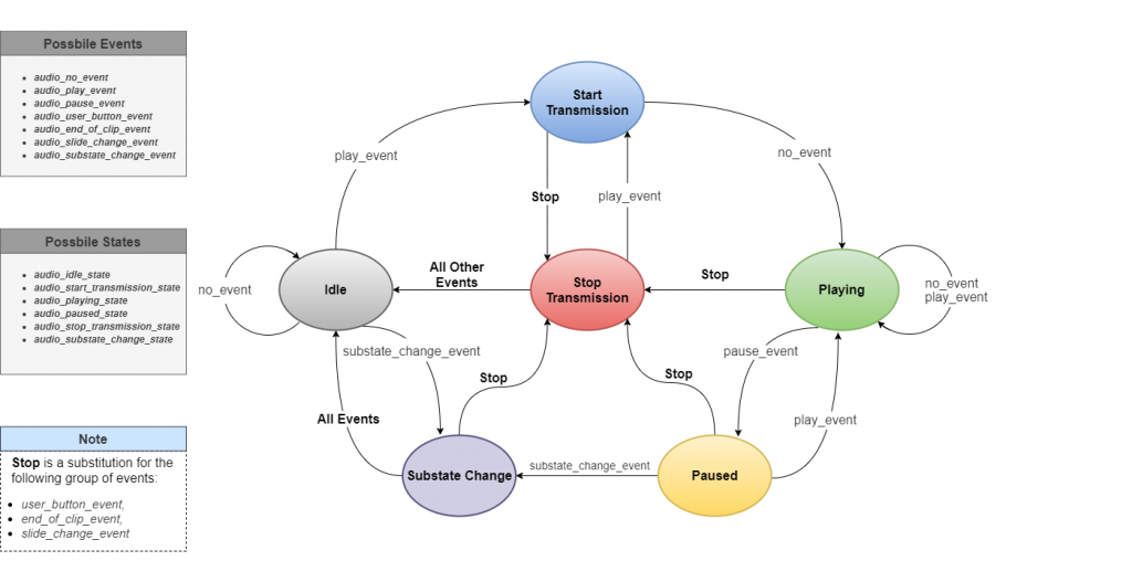
Audio State Machine
The audio state machine is meant to be used for multithreaded applications and runs alongside the main state machine in this system.
Looking at the diagram above, we see that it begins in an idle state. If a user is in a menu that plays sound (see GUI), they can invoke a play_event by pushing a specific virtual button. This transitions the audio state machine to the start_transmission_state, where it does a handshake with the SD Card to find the file, parses the header for length information, then begins a data stream of the audio clip.
From here the user interacts with the menu buttons to do things like invoke a pause_event (clicking the pause button). An important note here is that the audio state machine always wants to go back to the idle_state, since the SD Card is a shared resource and no other thread can access it while audio is playing.
The stop_transmission is also one of the most important states since it safely brings the audio stream to a halt. If we simply went back to the idle state, another thread (like the main system state machine) could attempt to access the SD Card. This would cause it to lock up and crash, since it still thinks it’s in the middle of a multiple block read.
The following two functions are serviced every iteration of the main loop:
/*!
* @brief Transition the audio's state machine based on the current state and events given
*        by the system's various menus.
* @param[in] NONE
* @return  NONE
*/
e_audio_state
states_audio_state_transition_handler(void)
{
   static e_audio_state audio_transition_table[audio_max_state][audio_max_event] =
   {
         /* no event                      play                            pause
          * user_button                   end-of-clip                     slide-change
          * substate-change                                                                  */

         //Idle
         {audio_idle_state,               audio_start_transmission_state, audio_idle_state,
          audio_idle_state,               audio_idle_state,               audio_idle_state,
          audio_substate_change_state},
         //Start transmission
         {audio_playing_state,            audio_playing_state,            audio_paused_state,
          audio_stop_transmission_state,  audio_stop_transmission_state,  audio_stop_transmission_state,
          audio_substate_change_state},
         //Playing
         {audio_playing_state,            audio_playing_state,            audio_paused_state,
          audio_stop_transmission_state,  audio_stop_transmission_state,  audio_stop_transmission_state,
          audio_substate_change_state},
         //Paused
         {audio_paused_state,             audio_playing_state,            audio_paused_state,
          audio_stop_transmission_state,  audio_stop_transmission_state,  audio_stop_transmission_state,
          audio_substate_change_state},
         //Stop Transmission
         {audio_idle_state,               audio_start_transmission_state, audio_idle_state,
          audio_idle_state,               audio_idle_state,               audio_idle_state,
          audio_idle_state},
         //Substate Change
         {audio_idle_state,               audio_idle_state,               audio_idle_state,
          audio_idle_state,               audio_idle_state,               audio_idle_state}

   };


   //Get the next state based on the current audio state and event
   e_audio_state tmp_current_audio_state = states_get_current_audio_state();
   e_audio_event tmp_current_audio_event = states_get_current_audio_event();
   e_audio_state tmp_next_audio_state = audio_transition_table[tmp_current_audio_state][tmp_current_audio_event];
   states_set_current_audio_state(tmp_next_audio_state);

   return(tmp_next_audio_state);
}
The actual implementation is carried out very similarly to the main system state machine. In the code above, we see that there is an audio state transition handler which has a 2D array of states. By looking at the current audio state and the current audio event, the function knows exactly how to transition.
/*!
* @brief This services any audio clip that may be running. It is also responsible
*        for stopping audio transmissions safely (not locking up the SD card)
*        upon state transitions and various events.
* @param[in] NONE
* @return  NONE
*/
void
states_update_audio(void)
{
   static uint8_t tmp_previous_slide = 0;
   uint8_t tmp_current_slide = states_get_current_slide_number();
   static e_substate previous_substate = substate0 ;
   e_substate tmp_current_substate = states_get_substate();
   static uint8_t early_termination_flag = 0;

   //If the user has selected a menu option, give a click sound before advancing
   // to the next substate
   if((previous_substate != tmp_current_substate) ||
      (tmp_previous_slide != tmp_current_slide))
   {
      states_set_current_audio_event(audio_substate_change_event);
      early_termination_flag = 1;
   }

   //If the repeat button was pressed, tell the system the audio was cut off early
   else if(audio_end_of_clip_event == states_get_current_audio_event())
   {
      early_termination_flag = 1;
   }

   //Pressing the home or back button supersedes all other events, since the audio transfer needs to end to
   //avoid audio playing outside of its menu or worse, locking up the sd card. This is for reentrancy safety.
   uint8_t active_button = buttons_status(user_button_template,(sizeof(user_button_template) / sizeof(*user_button_template)));

   if(NO_BUTTON_PRESS != active_button)
   {
      states_set_current_audio_event(audio_user_button_event);
      early_termination_flag = 1;
   }

   //Get the next state based on the current audio state and event
   e_audio_state tmp_next_audio_state = states_audio_state_transition_handler();

   switch(tmp_next_audio_state)
   {
      static uint32_t total_blocks = 0; //Total blocks the current file takes up in the SD card

      case audio_idle_state:
         states_audio_idle();
         break;
      case audio_start_transmission_state:
         total_blocks = states_audio_start_transmission();
         break;
      case audio_playing_state:
      {
         uint8_t end_of_conversion = dac_service_audio(total_blocks, early_termination_flag);

         if(1 == end_of_conversion)
         {
            states_set_current_audio_event(audio_end_of_clip_event);
         }

         early_termination_flag = 0;
         break;
      }
      case audio_paused_state:
         states_audio_pause();
         break;
      case audio_stop_transmission_state:
         states_audio_stop_transmission();
         break;
      case audio_substate_change_state:
         states_audio_substate_change();
         break;
      default:
         break;
   }

   timers_update_audio_clock();
   previous_substate = tmp_current_substate;
   tmp_previous_slide = tmp_current_slide;
}
The second thing we need is something to carry out the actual tasks depending on the current state. The code above looks rather menacing at first, but it is actually fairly simple.
The first block consists of a series of if statements which are meant to override any current audio event by ones that are more important. These help make sure the system doesn’t accidently lock up the SD Card.
The next main portion of this code is just a switch statement that determines which function needs to be called based on the current audio state. For example, if we are in the audio_paused_state, we should call the states_audio_pause() function. Straightforward right?
By servicing this function every iteration of the main loop, the audio state machine makes sure the system runs smoothly and is never in danger of locking up the processor.
Setting Up DMA
Since our audio is stored in external FLASH, the MCU must do a lot of repetitive memory-management operations to pull the file from the SD Card, alter it, then spit it back out to the DAC. We’re going to use the direct memory access (DMA) of our STM32 to make our processor’s life a lot easier.
This fancy feature allows us to simply point to two locations in memory (including peripherals) and have built in hardware do an independent data transfer. Our processor never has to get bogged down and can sit back watching Seinfeld reruns while the DMA does all the hard work.
/*!
* @brief Initializes DMA1 to trigger from timer5 and output to the DAC
* @param[in] NONE
* @return NONE
*
*/
void
dac_dma1_init(void)
{
   //Enable main DMA clock
   RCC->AHB1ENR |= RCC_AHB1ENR_DMA1EN;

   //Couple DAC to DMA
   DAC->CR |= DAC_CR_DMAEN1;

   // Set DMA to increment memory, interrupt on transfer complete, circular mode,
   //direction: memory to peripheral, channel 7 select, 512-byte transfers.
   DMA1_Stream5->NDTR = 512;
   DMA1_Stream5->CR |= (DMA_SxCR_MINC | DMA_SxCR_TCIE | DMA_SxCR_DIR_MEM_TO_PERIPHERAL | DMA_SxCR_CHSEL_CHANNEL7);

   //Source and destination registers are 16bit
   DMA1_Stream5->CR |= (DMA_SxCR_MSIZE_0 | DMA_SxCR_PSIZE_0);

   //Send to 12-bit right aligned DAC output register
   DMA1_Stream5->PAR = (uint32_t)&(DAC1->DHR12R1);

}
Although using DMA to both pull data from the SD Card and to transfer it to the DAC after processing would be the ideal scenario, we’re only going to do the latter. The code above sets our DMA transfers up with the following configuration:
- Memory to peripheral
- Interrupt on transfer complete
- 512-byte transfers
- 16-bit transfers
- Destination: DAC1
DAC
The audio amplifier circuit for our system is fed directly from the STM32’s digital to analog converter (DAC). This peripheral takes a digital value from our processor’s memory, let’s say 205, and changes it to a real-world voltage on the output, 3v for example. By feeding it a series of digital values, we can recreate an audio clip.
So how does our system feed the DAC these values?
/*!
* @brief Sends sound clip from SD card to LCD
* @param[in] total_blocks Total memory blocks in the SD card that the audio file takes up
* @param[in] tmp_early_termination_flag This tells the function whether the last audio was
*                      cut off early and the "current block number" needs to be reset
* @return transmission_complete A flag used to tell the audio state machine that the
*                               current sound clip has ended
*/
uint8_t
dac_service_audio(uint32_t total_blocks, uint8_t tmp_early_termination_flag)
{
   //Enable the DMA -> DAC clock and timer11 in case the audio just came out of
   // a paused state
   dac_enable();
   TIM5->CR1 |= TIM_CR1_CEN;
   timers_timer11_enable();

   static uint16_t buffer_ping[512] = {0};
   static uint32_t block_number = 0;
   static uint16_t buffer_pong[512] = {0};
   static uint16_t *p_current_buffer = buffer_ping;
   static uint16_t *p_dormant_buffer = buffer_pong;
   static uint16_t *p_tmp_swap_placeholder = NULL;

   uint8_t transmission_complete = 0;

   //If the last audio broke before it was done playing, block number needs to be reset so
   // that the current audio plays for its full length
   if(tmp_early_termination_flag)
   {
      block_number = 0;
   }

   if(block_number < total_blocks)
   {

      //Wait for DMA to transfer the contents of current buffer
      while(0 == g_dma_transfer_complete_flag) {}

      //Toggle current buffer
      p_tmp_swap_placeholder = p_current_buffer;
      p_current_buffer = p_dormant_buffer;
      p_dormant_buffer = p_tmp_swap_placeholder;

      g_dma_transfer_complete_flag = 0;

      //Reinitialize the DMA with the new buffer address and enable it
      DMA1_Stream5->NDTR = 512;
      DMA1_Stream5->M0AR = (uint32_t)p_current_buffer;
      DMA1_Stream5->CR |= DMA_SxCR_EN;

      //Burn through the CRC bits and wait until SD card sends data valid token
      while(SD_CMD17_TOKEN != spi_receive_byte(0xFF)) {} //CMD17 token is the same as CMD18, 0xFE

      uint8_t tmp_volume = dac_get_volume();

      //Fill the inactive buffer with the next block of data
      for(uint16_t current_byte = 0; current_byte < 512; current_byte++)
      {
         *(p_dormant_buffer + current_byte) = (((uint16_t)(spi_receive_byte(0xFF))) << tmp_volume);
      }

      block_number++;
   }

   else
   {
      block_number = 0;
      transmission_complete = 1;
   }

   return(transmission_complete);

}
Okay, let’s ignore everything in the function above except the main while loop for a second. This uses a ping-pong buffer, an implementation found in systems where data is constantly being received and simultaneously transmitted.
We start off by creating two large arrays (buffers), buffer_ping and buffer_pong, that we want to hold audio data. We also create three pointers (p_tmp_swap_placeholder, p_current_buffer, and p_dormant_buffer). Our DMA source gets set to buffer_ping via the pointer p_current_buffer and is enabled. This simply means it will take the contents of buffer_ping and spit them out, one-by-one to the DAC.
While buffer_ping is being transferred (remember the DMA is doing the work, not our processor), we fill buffer_pong (via p_dormant_buffer) with 512 bytes directly from the SD Card. The next time the function is called, the active and dormant buffers are swapped. This means that now buffer_pong (which we filled on the last function call) will be active and get sent to the DAC while buffer_ping is filled with a fresh new batch of 512 bytes from the SD Card. This process repeats itself until the entire audio file has been transferred. Not too complicated, right?
So, what about the rest of the function? The tmp_early_termination_flag is passed to the function via the audio state machine and lets it know if the previous audio was cut off (the user pressed the home button etc.) while playing. This is important because block_number needs to be reset, or it will still think that it is in the middle of the old audio clip and the current audio will end prematurely.
Finally, everything at the top regarding TIM5 is simply referring to the fact that Timer 5 is the 22kHz clock source for the DMA/DAC and needs to be enabled for data to be transferred. Timer 11 is used to keep track of how many seconds have passed since the audio started playing, which is displayed in the GUI.
Volume
“So,” you inquire, “if all audio in the system is 8 bits, why is the DMA feeding a 12-bit DAC register?” Glad you asked. You may have noticed in the code above that all audio values coming from the SD Card are getting shifted.
*(p_dormant_buffer + current_byte) = (((uint16_t)(spi_receive_byte(0xFF))) << tmp_volume);
Well, this is so that the user can dynamically change volume. We can align our 8-bit audio bytes however we want inside of the 12-bit register as long as no bits are hanging off the edge. Take a look at the diagram below:
Here we can see how the 12-bit DAC register gets filled at different volume levels (tmp_volume). By only shifting the data, we avoid aliasing the audio (quantization error etc.) while allowing the DAC to output at different levels. Pretty cool, huh?
